Acoustooptic filter
a technology of acoustical filter and acoustic filter, which is applied in the direction of instruments, non-linear optics, optics, etc., can solve the problems of low electrical power, inability to provide a flat wavelength transmission characteristic over a broad band,
- Summary
- Abstract
- Description
- Claims
- Application Information
AI Technical Summary
Benefits of technology
Problems solved by technology
Method used
Image
Examples
first embodiment
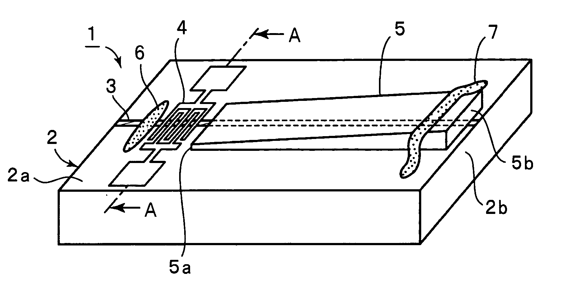
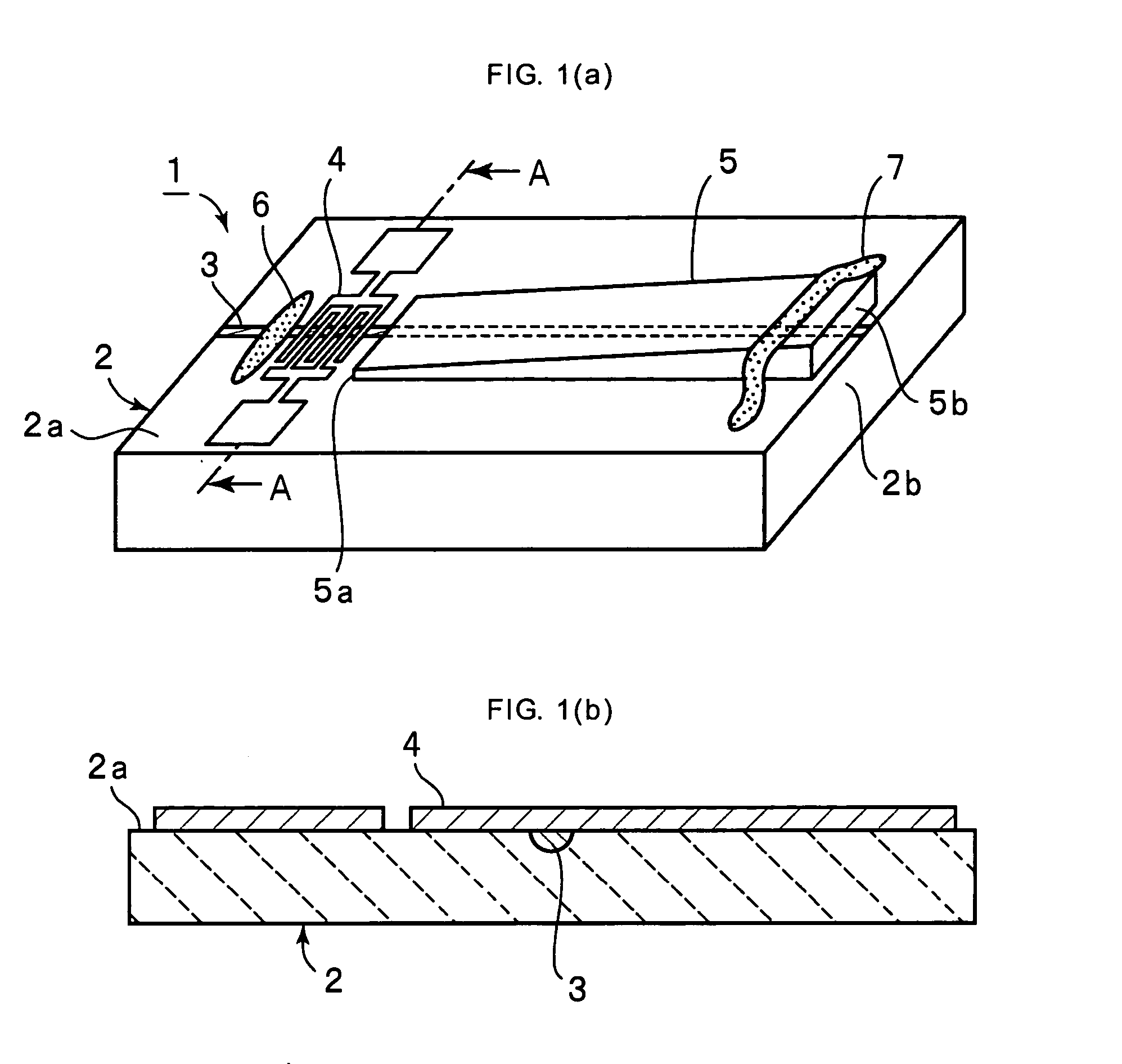
[0053]FIG. 1(a) is a perspective view of an acoustooptic filter according the present invention, and FIG. 1(b) is a schematic sectional view taken along line A-A shown in FIG. 1(a). An acoustooptic filter 1 has an X-cut Y-propagating LiNbO3 piezoelectric substrate 2.
[0054] An optical waveguide 3 is formed in a widthwise-direction central portion of an upper surface 2a of the piezoelectric substrate 1 so as to extend longitudinally. The optical waveguide 3 is formed by thermally diffusing Ti. In the embodiment, the optical waveguide 3 is formed in an area having a width of 90 nm at the central portion of the upper surface 2a of the piezoelectric substrate 2 by thermally diffusing Ti for 8 hours at a temperature of 1040° C. The optical waveguide 3 is formed over the entire longitudinal-direction length at the upper surface 2a of the piezoelectric substrate 2. The length of the piezoelectric substrate 2 is 60 mm, and its width is 5 mm.
[0055] An interdigital electrode IDT 4 for excitin...
second embodiment
[0076] In the acoustooptic filter 21 the pair of wall surfaces 22a and 23a for reflecting a surface wave are provided, thereby forming a surface wave waveguide for a surface acoustic wave excited at the IDT 4. Since the lengths of the pair of wall surfaces 22a and 23a change in the longitudinal direction of the mutual action area, the phase speed of the surface wave changes at the surface wave waveguide. Therefore, the aforementioned phase match condition changes by approximately 1%.
[0077] Consequently, similarly to the acoustooptic filter 1 according to the first embodiment, since the phase match condition is changed by the wall members 22 and 23, it is possible to a achieve a broader light transmission band characteristic without reducing the mutual action area length.
[0078] Although, in the second embodiment, the heights of the wall surfaces 22a and 23a change along the longitudinal direction of the mutual action area, the distance between wall surfaces 32a and 33a of respectiv...
third embodiment
[0080]FIG. 8 is a perspective view of an acoustooptic filter according to a
[0081] An acoustooptic filter 41 has the same structure as the acoustooptic filter 1 except that, instead of the thin-film ridge 5, a phase speed control film 42 is provided on a piezoelectric substrate 2. Here, the phase speed control film 42 is formed by sputtering ZnO, and has a length of 30 nm in a longitudinal direction of a mutual action area and has a width equal to the overall width of the piezoelectric substrate 2.
[0082] The phase speed control film 42 becomes thicker from an end 42a adjacent to an IDT 4 to an opposite end 42b. More specifically, the thickness at the end 42a is 0.4 μm, and the thickness at the end 42b is 1.0 μm.
[0083] In the acoustooptic filter 41, the phase speed control film 42 causes the phase speed of a surface acoustic wave to change as in the acoustooptic filter 1, so that the phase match condition changes by approximately 1%.
PUM
| Property | Measurement | Unit |
|---|---|---|
| temperature | aaaaa | aaaaa |
| width | aaaaa | aaaaa |
| width | aaaaa | aaaaa |
Abstract
Description
Claims
Application Information
 - R&D
- Intellectual Property
- Life Sciences
- Materials
- Tech Scout
- Unparalleled Data Quality
- Higher Quality Content
- 60% Fewer Hallucinations
Browse by: Latest US Patents, China's latest patents, Technical Efficacy Thesaurus, Application Domain, Technology Topic, Popular Technical Reports.
© 2025 PatSnap. All rights reserved.Legal|Privacy policy|Modern Slavery Act Transparency Statement|Sitemap|About US| Contact US: help@patsnap.com


