Numerical controller
a controller and number technology, applied in the direction of electric programme control, automatic control, instruments, etc., can solve the problems of servomotor and control axis speed reduction and sharp increase, servomotor cannot move smoothly, and the speed of servomotor and control axis is once reduced and then sharply increased, and achieves a rapid change of speed
- Summary
- Abstract
- Description
- Claims
- Application Information
AI Technical Summary
Benefits of technology
Problems solved by technology
Method used
Image


Examples
first embodiment
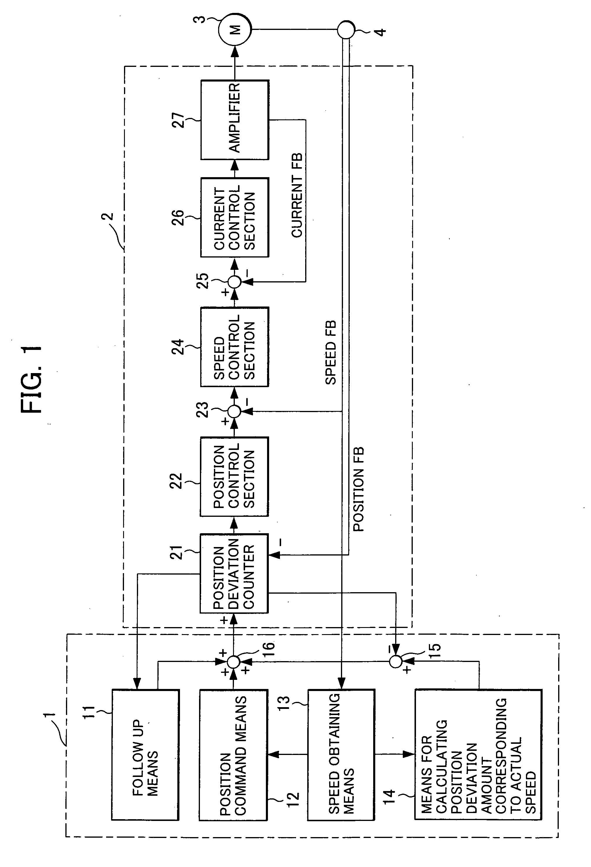
[0034]a numerical controller of the present invention will be explained using FIGS. 1 to 6.
[0035]The numerical controller shown in FIG. 1 includes a numerical control section 1 and a servo control section 2, like a conventional numerical controller. The servo control section 2 carries out position / speed control of a servomotor 3 based on a move command sent from the numerical control section 1 and further carries out a current loop control to control a position and speed of the servomotor (control axis driven by the servomotor). The numerical controller is different from the conventional numerical controller in that the numerical control section 1 also includes speed obtaining means 13, calculating means 14 which calculates a position deviation amount corresponding to an actual speed, and adder-subtractors 15 and 16, and in that the distribution processing of move command is carried out with an initial speed set to the current actual speed in servo-on state in the position command m...
second embodiment
[0065]the numerical controller of the present invention will be explained using FIG. 7.
[0066]The second embodiment is different from the first embodiment in that storing means 17 for storing actual speed obtained by the speed obtaining means 13, and speed predicting means 18 for predicting the actual speed in the current distribution period from the actual speed stored in the storing means 17 are added. Other portions of the second embodiment are the same as those of the first embodiment.
[0067]The actual speed of the control axis (servomotor) is detected by the position / speed detector 4, but since the detection is delayed generally, the obtained actual speed is old information. When the control axis motion is in a steady state and the speed is not varied, there is no problem even if the detected speed is used as the actual speed. However, when the control axis (movable portion) is pushed out by external force in servo-off state, the control axis is in the transient state, the speed ...
third embodiment
[0073]the numerical controller of the present invention will be explained using FIGS. 8 and 9.
[0074]The third embodiment is different from the first embodiment in that the numerical controller of the third embodiment also includes averaging means 19 for averaging an obtained actual speeds, and maximum speed detecting means 20, and in that the maximum speed detecting means 20 outputs a servo-on signal. Other portions of the third embodiment are the same as those of the first embodiment.
[0075]In a die-casting machine or a press machine, when a mold is to be opened, a movable mold (control axis) driven by a servomotor and a workpiece are pushed out from a stationary mold by means of a hydraulic pressure apparatus while the servomotor is in a servo-off state, and the servomotor gets into servo-on state in a state where the movable mold is pushed out and is coasting so that position of the movable mold (control axis) is controlled. In that case, it is preferable that the servomotor gets ...
PUM
| Property | Measurement | Unit |
|---|---|---|
| speed | aaaaa | aaaaa |
| current | aaaaa | aaaaa |
| speeds | aaaaa | aaaaa |
Abstract
Description
Claims
Application Information
 - R&D
- Intellectual Property
- Life Sciences
- Materials
- Tech Scout
- Unparalleled Data Quality
- Higher Quality Content
- 60% Fewer Hallucinations
Browse by: Latest US Patents, China's latest patents, Technical Efficacy Thesaurus, Application Domain, Technology Topic, Popular Technical Reports.
© 2025 PatSnap. All rights reserved.Legal|Privacy policy|Modern Slavery Act Transparency Statement|Sitemap|About US| Contact US: help@patsnap.com