
Testing method and apparatus ground liquefaction and dynamic characteristics in original position utilizing boring hole

a testing method and apparatus technology, applied in the field of testing methods and apparatus, can solve the problems of out of scope for its use, machinery vibration, and difficult to perform soil sampling in an undisturbed manner, and achieve the effects of rapid change in the displacement of the bore-hole wall, time and cost saving, and soil properties can also be examined

Inactive Publication Date: 2007-06-28
MASUDA GIKEN
View PDF4 Cites 8 Cited by
  • Summary
  • Abstract
  • Description
  • Claims
  • Application Information

AI Technical Summary

Benefits of technology

[0028] As described above, the testing method and apparatus in the present invention enable us to perform in-situ testing on natural soil deposits without sampling of soils deep in the deposits, and to evaluate therefore the dynamic properties of natural soil deposits.
[0029] This testing method and apparatus can be used to a wide range of soil types, including loose sand deposits and gravel-containing soil deposits which are difficult to perform soil sampling, and also soil deposits involving large-sized grains such as sandy gravels, weathered rocks and soft rocks.
[0030] This testing method is also time and cost-saving in comparison to the conventional soil sampling.
[0031] This testing apparatus can perform a variety of tests by applying the cyclic pressures alternately to multiple locations along the depth of a bore-hole wall. These kinds of tests are supposed to produce soil elements in the deposit which are either suspected to cyclic compressional stress or subjected to cyclic shear stress at the periphery of the cells. Since soil liquefaction during earthquakes is effectively induced by the action of cyclic shear stress on the soil deposit, this testing method and apparatus are considered useful in the assessment of liquefaction occurrence. When the soil element located at the periphery of the cells is subjected to collapse due to liquefaction, the liquefaction propagates into the region of the soil deposit subjected to compressional stress leading to a rapid change in the displacements of the bore-hole wall.
[0032] Another testing method is to perform cyclic loading tests by using only one of the cells in the zonde. From this kind of tests, it is also possible to examine a variety of properties of the soil deposits. In such cases, the cyclic loading can be conducted by the combination of one or more types of loading chosen from compressive loading acting towards the radial direction, torsional loading acting around the bore-hole axis and shear loading acting towards the bore-hole axis.
[0033] Since there are two guard cells located above the top cell and beneath the bottom cell, the pressure - displacement relations can also be monitored at these two guard cells. By analyzing these data monitored at the two guard cells in comparison to the data obtained at the central cell, the soil properties can also be examined. In addition, the two guard cells assist in producing a stable condition to perform cyclic loading at the top and bottom cells.

Problems solved by technology

However, the conventional testing method was intended only to infer the static properties of the soil deposit, and the evaluation of the dynamic properties of the soil deposit, such as those under earthquake loading, traffic loading and machinery vibrations, was out of scope for its use.
In the event of earthquakes, however, the strains gradually accumulate locally within the soil deposit leading in some cases to failures, due to the external forces associated with earthquakes, which might be even lower than the collapse loads.
However, it is extremely difficult to perform soil sampling in an undisturbed manner while preserving soil structures in natural deposits during sampling.
It is therefore difficult to precisely evaluate the in-situ properties of the soil deposit in laboratory tests.
In addition, the undisturbed sampling methods for loose sand deposits, gravel-containing soil deposits, soil deposits involving large-sized grains such as sandy gravels, weathered rocks and soft rocks are not well established, and hence it is not practically possible to perform laboratory tests on such soil deposits.
In the current state of practice, it is therefore found that the range of soils that can be supplied to laboratory tests is extremely limited.

Method used


Image

  • Testing method and apparatus ground liquefaction and dynamic characteristics in original position utilizing boring hole
  • Testing method and apparatus ground liquefaction and dynamic characteristics in original position utilizing boring hole
  • Testing method and apparatus ground liquefaction and dynamic characteristics in original position utilizing boring hole

Examples


example 1

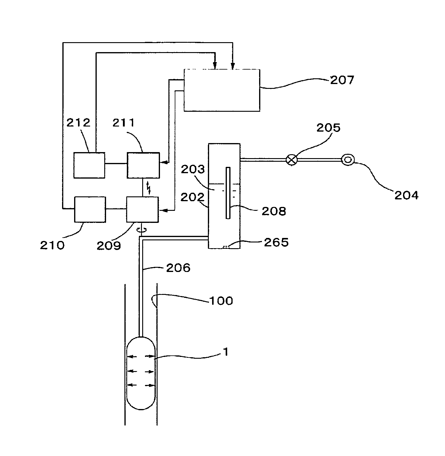
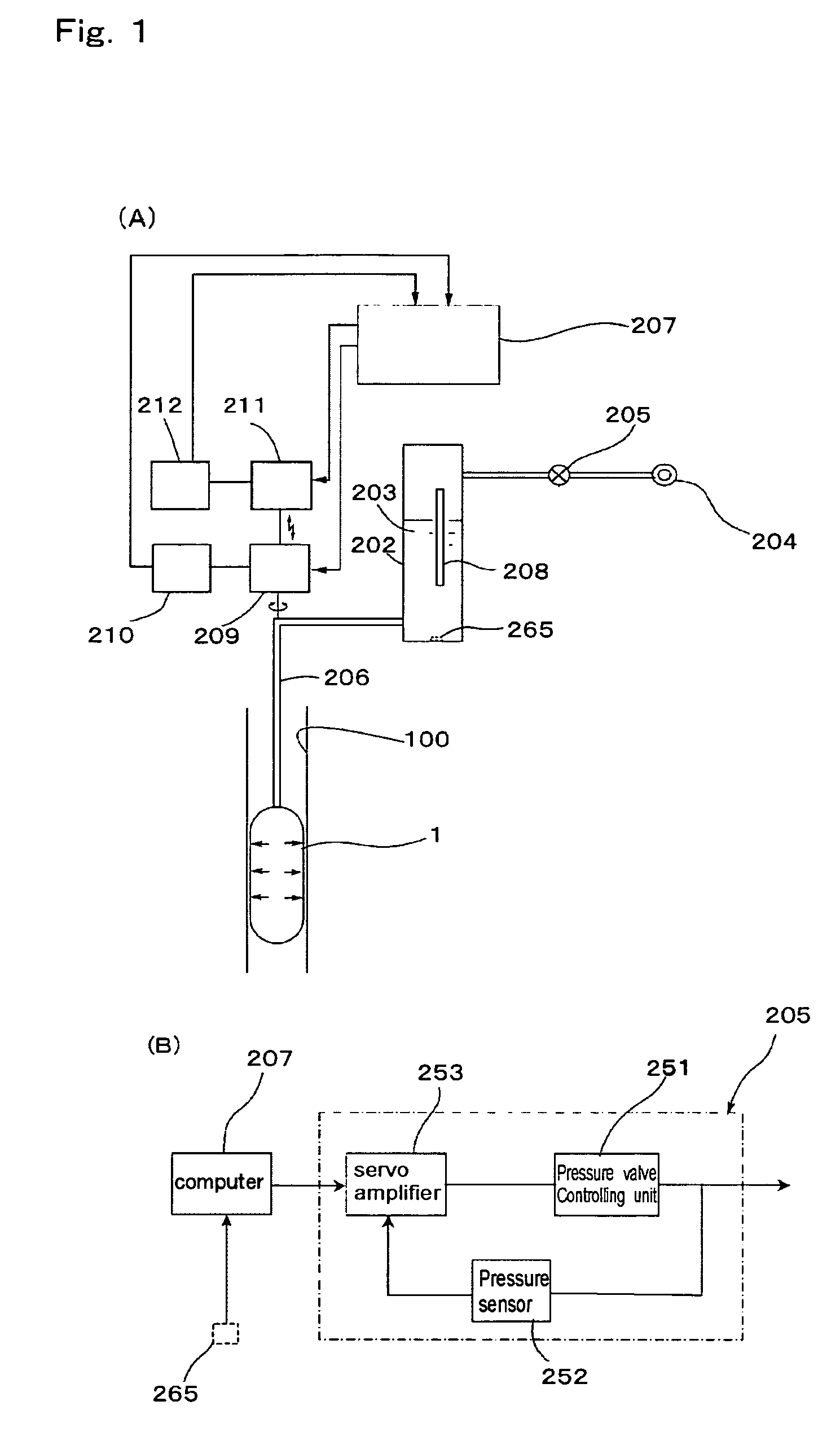
[0040]FIG. 1(A) shows the schematic illustration of the testing apparatus materializing the working example 1.

[0041] This testing apparatus is composed of an inflatable membrane zonde 201, which is lowered down into a bore-hole 100, and apply the pressures onto a bore-hole wall via a liquid medium such as water 203 in the zonde 201, a control unit which can pressurize the liquid medium such as water 203 in the zonde 201, and fluctuate periodically the amplitudes of the pressures in the zonde 201 via a pressure regulator 205, and a device 208 which implements the measurement of the displacements of the bore-hole wall.

[0042] In the working example, the water 203 is reserved in the tank 2 on the ground surface. The pressurized air is supplied to a top portion of the water tank 202 from the pressure supplying unit 204. This pressurized air is supplied via the pressure regulator 205 to the water 203 stored in the Water tank 202. Instead of regulating the air pressure, the Water pressur...

working example 2

[0080] The working example 2 is described below.

[0081]FIG. 7 shows the general layout of the in-situ testing apparatus in the present invention, which is aimed at exploring the dynamic properties of soils using bore-holes.

[0082] In the working example 1 described above, the cyclic loading is employed only on one location with a single cell of the zonde. However, in the working example 2, the cyclic loading is alternatively imposed on the top and bottom parts of the soil layer, J1 and J3, in such a manner that the soil element at the central part, J2, is subjected to cyclic shear stress.

[0083] Herein, the membrane zonde 110, which is lowered down into a bore-hole 100, is composed of three independent cells, 1st Cell 111, 2nd cell 112 and 3rd cell 113, which are failed with a liquid medium. The 1st cell 111 and 3rd cell 113 are alternatively cyclically excited by the 1st controlling device 121 and the 3rd controlling device 123, while the 2nd cell is statically pressurized by the 2...

working example 3

[0126] The working example 3 for the test apparatus aimed at exploring in-situ the liquefaction and dynamic characteristics of soils using bore-hole is described.

[0127] In the above working example 2 the zonde which is inserted into a bore-hole is made up of separate multiple cells, which can apply the pressures independently to the corresponding soil layers via liquid media filled in the cells. The pressure and displacement at the bore-hole wall at each cell are monitored. The zonde is made up of three cells, i. e. a central cell at which the static loading is applied, and top and bottom cells at which the cyclic loading is applied alternatively with one another. By applying the cyclic loading alternatively to the top and bottom cells, the pressure and displacement at the central cell is monitored and examined, which are supposed to undergo some effects of cyclic loading on the top and bottom cells.

[0128] However, the effects of cyclic loading imposed by the top and bottom cells ...


PUM


Abstract

A testing method and apparatus for ground liquefaction and dynamic characteristics in the original position utilizing a boring hole, wherein the dynamic strength and deformation characteristics of a soil layer against a dynamic repetitive load, in an optional position in the ground can be obtained by a simple method. A measuring cell based on a three-chamber construction is used, and upper and lower soil layers (J1, J3) with an intermediate soil layer (J2) therebetween are alternately subjected to a dynamic repetitive load, and what influence there is on the intermediate soil layer (J2) is investigated from the relation between pressure and displacement.

Description

TECHNICAL FIELD [0001] This invention relates to the testing method and apparatus, which are intended to evaluate in-situ the liquefaction and dynamic (strength and deformation) properties of soils using boreholes. Herein, the liquefaction and dynamic properties of soils correspond to those under dynamic cyclic loading such as earthquake loading, traffic loading and machinery vibrations. TECHNICAL BACKGROUND [0002] In the conventional in-situ testing method, a small-diameter bore-hole was produced down to a certain depth from the ground surface, and a cylindrically shaped zonde (inflatable membrane) was lowered down into the bore-hole. The zoned was then inflated and applied the lateral pressure to the surrounding circular wall of the soil deposit, based on the measurements of lateral pressure and radial displacement, the static strength and deformation properties of the soil deposit were inferred. [0003] However, the conventional testing method was intended only to infer the static...

Claims


Application Information

Patent Timeline
IPC IPC(8): E21B49/00E02D1/00G01N3/32G01N13/00
CPCE02D1/00G01N3/32G01N2013/006
Inventor MASUDA, KAZUO
Owner MASUDA GIKEN
Learn More