Linear stage including an integrated actuator and associated methods

a technology of integrated actuators and linear stages, applied in the field of translating stages, can solve the problems of inability to maintain the same speed (or linear motion) across low and high speed applications, and the like, which are used with conventional linear stage devices such as stepper motors, dc motors, etc., to achieve the effect of reducing friction and increasing the accuracy of the stage position

Inactive Publication Date: 2007-06-14
NEWPORT CORP
View PDF11 Cites 4 Cited by
  • Summary
  • Abstract
  • Description
  • Claims
  • Application Information

AI Technical Summary

Benefits of technology

[0011] The first portion may include a base portion of the stage device and the second portion may include a translating stage portion of the device. One or more sensors may be included to provide positional information of the relative movement of the stage portion and base portion. Such positional information may be used by a system to increase the accuracy of the stage position. Further, bearings such as mechanical bearings or fluid dynamic bearings may be disposed between relative moving parts of at the linear stage to reduce friction and the like.

Problems solved by technology

Additionally, the relative positioning of such optical components is often desirably achieved quickly, e.g., within a fraction of second.
Conventional actuators such as stepper motors, dc motors, or the like used with conventional linear stage devices generally do not have uniformity of speed (or linearity of motion) across low and high speed applications.
Further, conventional actuators for translating linear stages take up space adjacent to the latter and may require periodic maintenance, such as monitoring or replacing lubrication between moving portions of the actuator and the like.
Additionally, portions of the actuator that are in contact may further wear resulting in degradation of performance or failure of the device.
For example, surface hardening steps may be needed to lengthen the life and reliability of actuator elements in contact such as rolling or bearing elements, and the like.
Additionally, manufacturing tolerances of the linear stage and actuator may need to be very small to prevent build up of tolerances in the final stage device.

Method used


Image

  • Linear stage including an integrated actuator and associated methods
  • Linear stage including an integrated actuator and associated methods
  • Linear stage including an integrated actuator and associated methods

Examples


Embodiment Construction

[0021] The following description is presented to enable a person of ordinary skill in the art to make and use the various aspects and examples of the inventions. Descriptions of specific materials, techniques, and applications are provided only as examples. Various modifications to the examples described herein will be readily apparent to those of ordinary skill in the art, and the general principles defined herein may be applied to other examples and applications without departing from the spirit and scope of the inventions. Thus, the present inventions are not intended to be limiting to the examples described and shown, but are to be accorded the scope consistent with the appended claims.

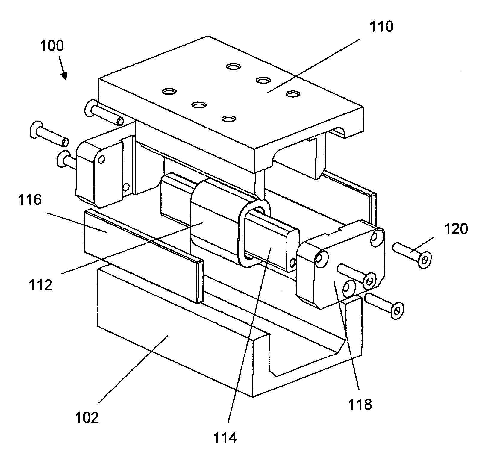
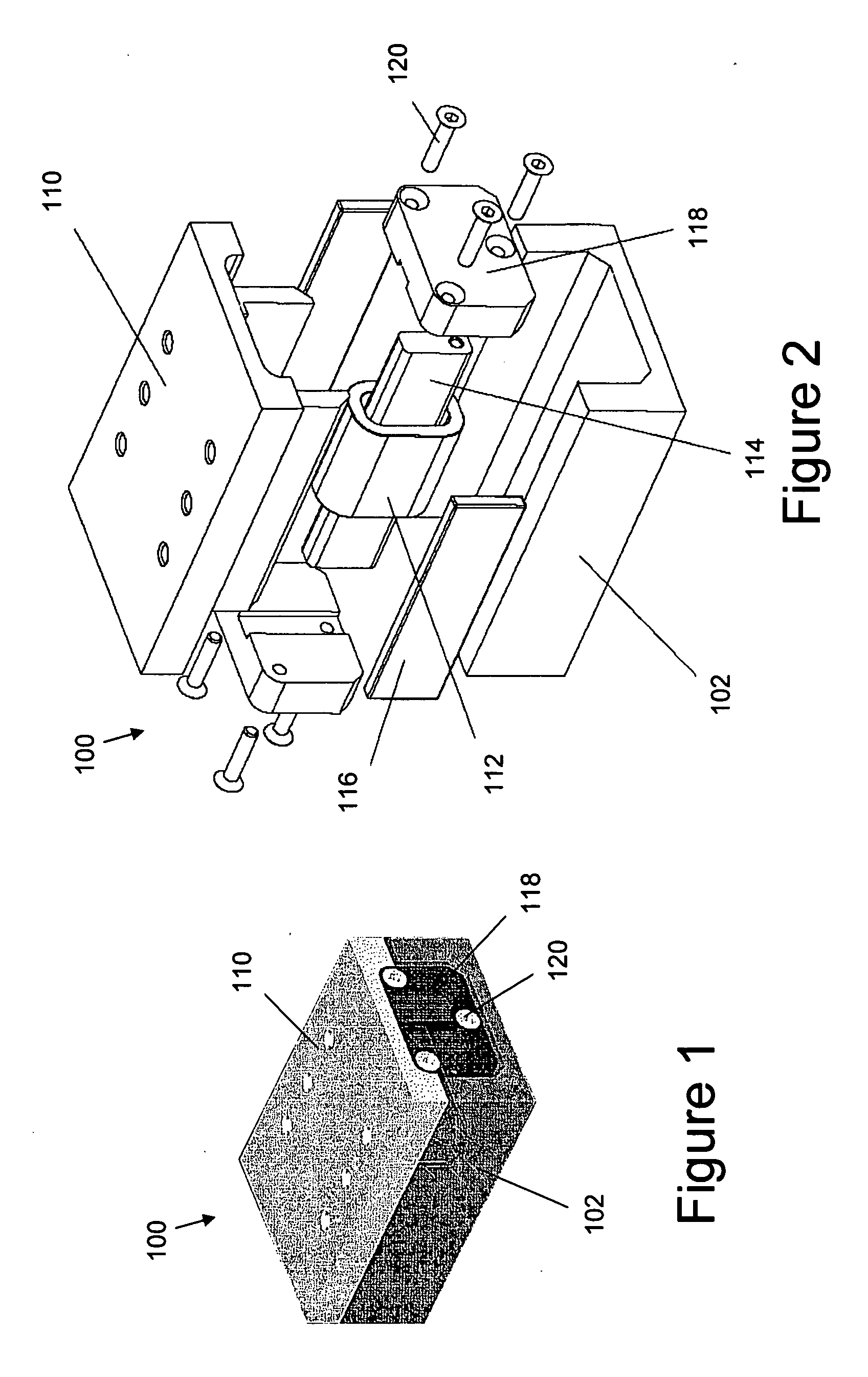
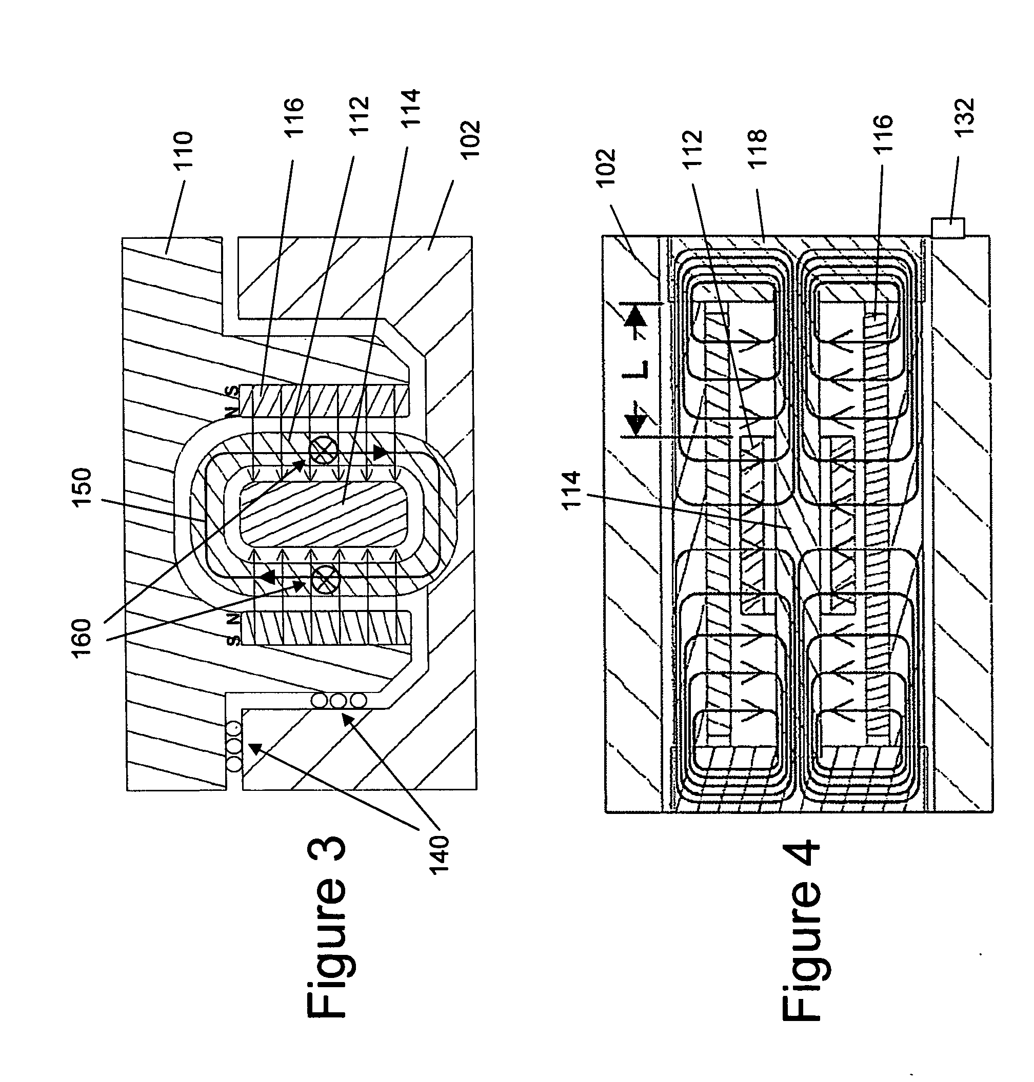
[0022] According to one aspect, an exemplary translational linear stage is provided herein. Broadly speaking, linear stages are devices which include a base and stage, wherein the base and stage are adapted for relative translation. An actuator is used to move the stage relative to the base. In o...


PUM

PropertyMeasurementUnit
magnetic fieldaaaaaaaaaa
magneticaaaaaaaaaa
ferromagneticaaaaaaaaaa

Abstract

According to one example a linear translation stage is provided. The linear stage includes a first portion (e.g., a base portion) and a second portion (e.g., a stage portion) configured for relative translation with respect to each other. One of the first portion or the second portion has a coil associated therewith and the other of the first portion or the second portion has a magnetic source associated therewith. The magnetic source may include one or more magnets to produce a magnetic field that generally encompasses the coil such that current through the coil causes a force on the coil, thereby causing translation of the first portion relative to the second portion.

Description

BACKGROUND [0001] 1. Field [0002] The present invention relates generally to translating stages, and more particularly to translating linear stages including integrated actuators and associated methods of manufacture. [0003] 2. Description of Related Art [0004] The use of adjustable mounting apparatus for supporting optical components, such as optical fibers, mirrors, beam splitters, lenses, gratings, and the like, is known. For example, it is frequently necessary to position a first optical element, such as an optical fiber or waveguide, relative to a second optical element, such as another optical fiber or waveguide, a microscope objective lens, or the like. Frequently, the relative positioning of such optical components is desirably very precise, with accuracy on the order of optical wavelength dimensions sometimes being necessary. Additionally, the relative positioning of such optical components is often desirably achieved quickly, e.g., within a fraction of second. [0005] Commo...

Claims


Application Information

Patent Timeline
Patent Type & Authority Applications(United States)
IPC IPC(8): G11B21/02
CPCG02B7/02G02B7/18
Inventor CHOI, DONG H.
Owner NEWPORT CORP
Why Eureka
Try Eureka