
Thermal cushion and device comprising such a cushion

Inactive Publication Date: 2007-06-14
WELLCARE PROD
View PDF39 Cites 11 Cited by
  • Summary
  • Abstract
  • Description
  • Claims
  • Application Information

AI Technical Summary

Benefits of technology

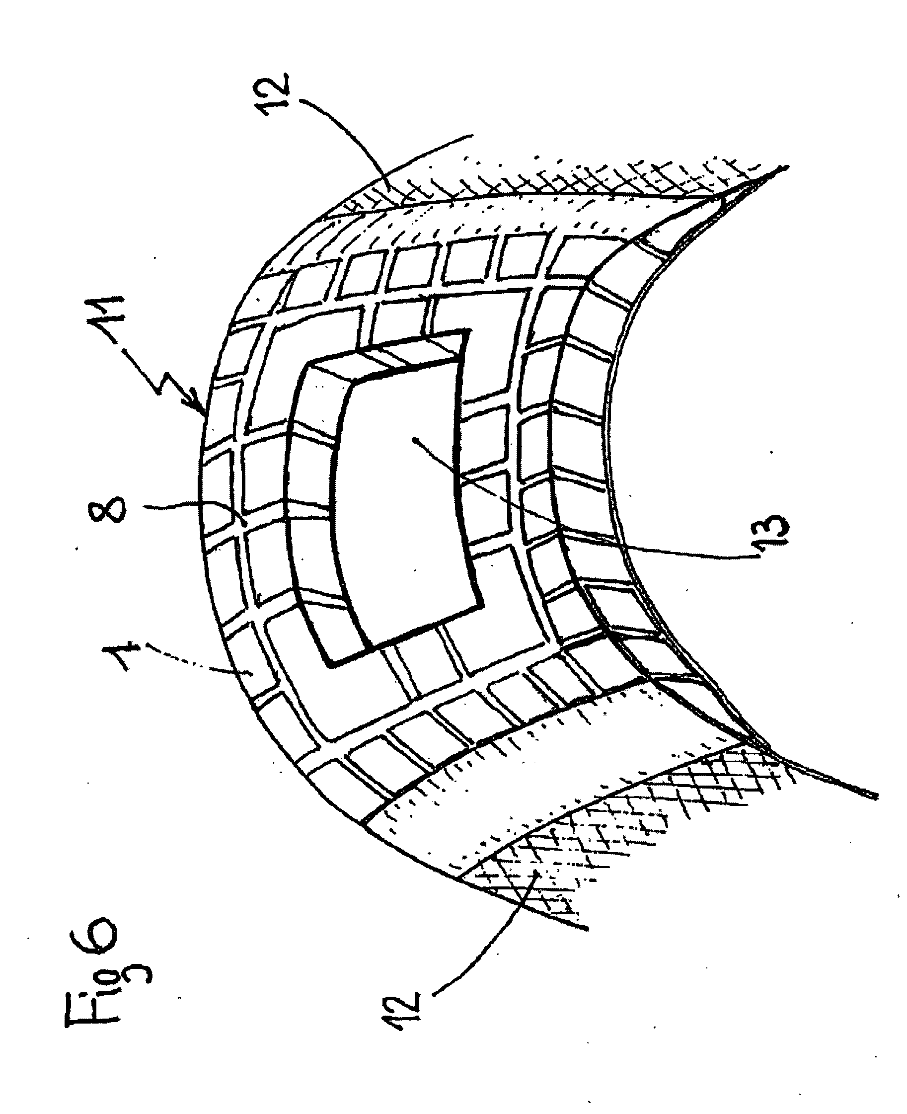
[0009] The invention aims to overcome the above-mentioned drawbacks of known thermal cushions and to meet the needs of potential users (in particular in a hospital environment) by providing a thermal cushion of a new design that combines excellent flexibility / elasticity with being able to adapt perfectly, even to forms in motion and with a high and lasting calorific value at a more or less constant temperature, whose action is homogeneous (especially when it is used on a part of the human body), whose thickness can be maintained more of less constant during use, whose size and shape are more or less unlimited, that can undergo major variations in pressure without deforming and that, thanks to its above-mentioned properties, can adapt to many different uses, in particular in a hospital environment, without requiring major handling.

Problems solved by technology

This known cushion has the drawback of being difficult and expensive to produce, its performances are weak and its applications limited.
These known cushions nevertheless have the drawback of requiring an expensive gel and their manufacture is delicate and costly.
On the other hand, it has the drawback of a short working life since the production of cold does not result from the latent heat of fusion but from the gradual reheating of the gel.
Moreover, the productivity of the cushion (the production of cold or the extraction of calories per unit of time) is not constant but decreases as the gel is reheated, which represents a further drawback for this known cushion.
For one thing, they reduce the thermal capacity of the panel and for another they present an obstacle to homogeneous action of the panel when the latter is applied onto a patient's skin.
These known thermal cushions have poor flexibility and are difficult to deform, mainly when the thermal fluid of the envelope is a liquid or a solid substance in the state of particles.
They are therefore ill-suited to uniform application on a human or animal limb.

Method used


Image

  • Thermal cushion and device comprising such a cushion
  • Thermal cushion and device comprising such a cushion
  • Thermal cushion and device comprising such a cushion

Examples


Embodiment Construction

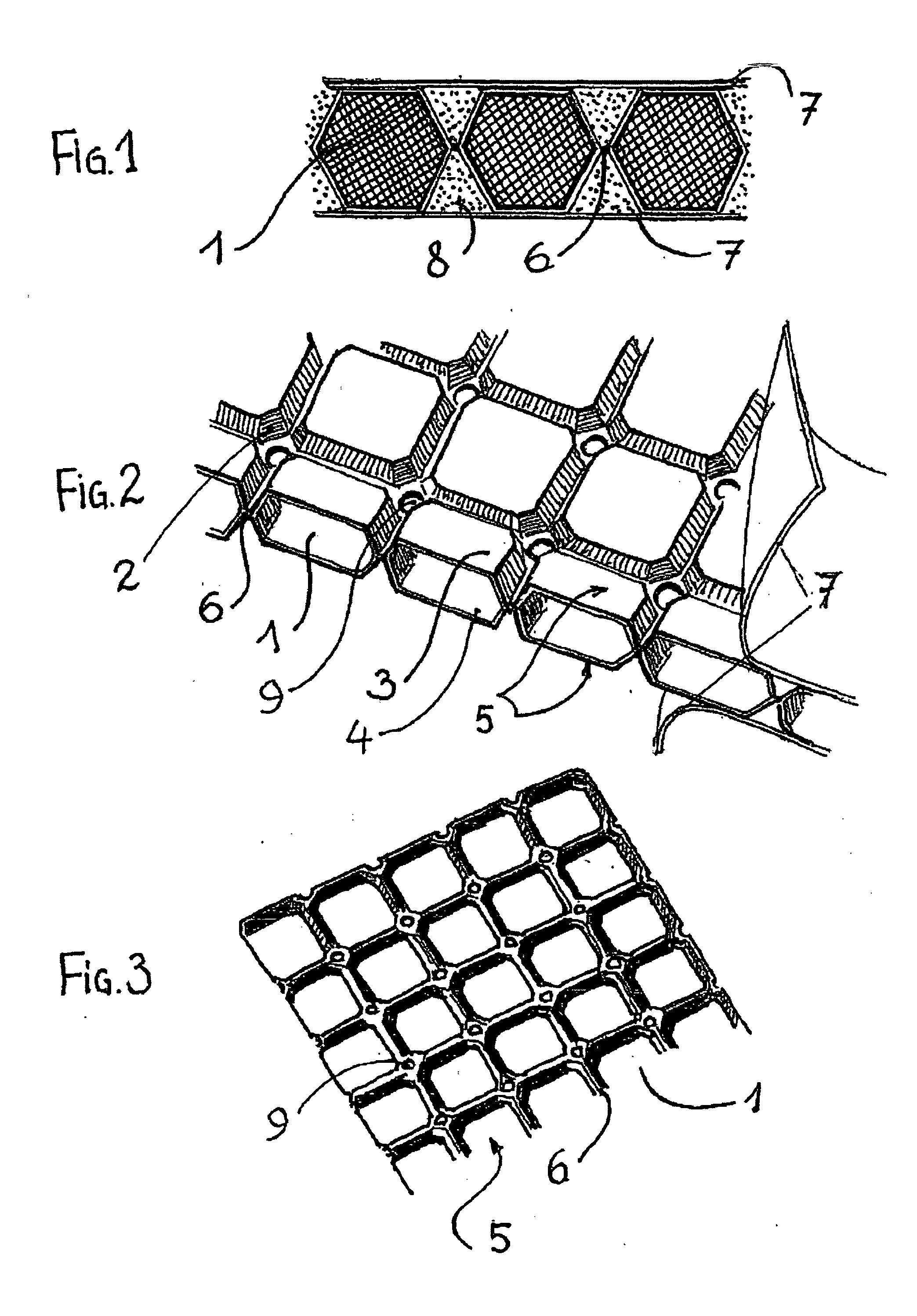
[0089] The thermal cushion shown in FIG. 1 and 2 comprises a network of blocks 1, formed by hollow cells. The blocks or cells 1 have the shape of prisms with square bases. Each cell 1 is formed by two truncated pyramids 3 and 4, attached along their long square bases. The side ridges of the two truncated pyramids have bevelled edges (2). The network of cells 1 is formed by the assembly of two corrugated sheets 5 in a flexible polymer material (for example in plastified polyvinyl chloride or in styrene-ethylene-butyl-styrene copolymer) pre-drawn and welded to each other along tongues 6 between the cells (a corrugated sheet 5 is shown in FIG. 3). The tongues 6 are flexible and elastic and they act as articulations between the cells 1. They are pierced by apertures 9 whose function will be explained later on. By bending or twisting the assembly of sheets 5, the cushion of cells may thus adopt complex profiles to fit an appropriate body, for example part of the anatomy of a human being ...


PUM


Abstract

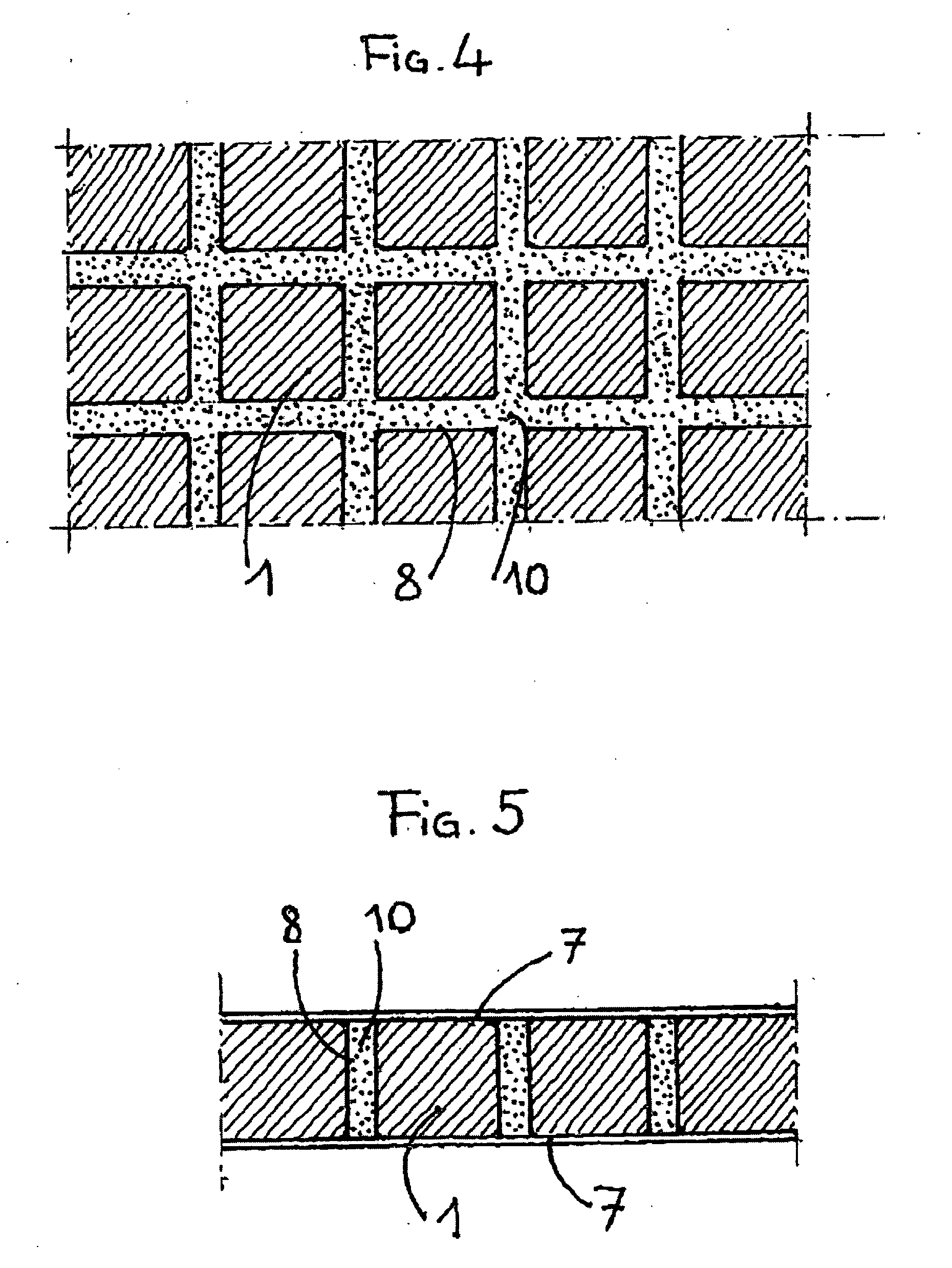
The inventive heating cushion consists of a system of blocs (1) which comprise a thermal material, are separated by interstices (8) containing a deformable thermal material (10), are connected by joints provided with elastic solid bodies which are fixed to the blocs and form said deformable thermal material and / or elastic membranes (7) which are fixed to the blocs (1) and are tensioned for compressing a deformable body arranged in the interstices (8) and / or the joints (6) which are permeable to a fluid contained in the interstices.

Description

FIELD OF THE INVENTION [0001] The invention relates to thermal cushions and to their use. STATE OF THE ART [0002] The hospital sector and ambulatory medicine are major users of thermal cushions, in particular for external thermal regulation and in order to relieve pain or in various therapies such as for example cryotherapy. [0003] Indeed, it is known that the application of cold can relieve pain (headaches, migraine, toothaches, muscular or inflammatory pains, etc.) or encourage the resorption of hematomas, edemas and the healing of accidental or surgical wounds. [0004] U.S. Pat. No. 3,545,230 proposes a coolant cushion that uses the latent heat of fusion of a solid substance. During this fusion phase, the temperature remains constant. The cushion comprises a layer of insoluble and hydrophilic gel in a sealed and flexible envelope. An inert and flexible substrate (for example fibres or a fabric), immersed in the gel, serves to strengthen the mechanical resistance of the cushion and...

Claims


Application Information

Patent Timeline
IPC IPC(8): E04H15/20A61F7/02
CPCA61F7/02A61F2007/0002A61F2007/0029A61F2007/0039A61F2007/0062A61F2007/0268
Inventor JOUHANNET, GUY
Owner WELLCARE PROD
Learn More