Doped fiber scene projection system and method

a fiber scene and fiber projection technology, applied in the direction of waveguides, picture reproducers using projection devices, instruments, etc., can solve the problems of resistor array technology not meeting the requirements of such testing, limited temperature simulation by the array, and prior art resistive approaches can only generate “cool” scenes, not “hot”

Inactive Publication Date: 2007-06-07
THE UNITED STATES OF AMERICA AS REPRESENTED BY THE SECRETARY OF THE NAVY
View PDF2 Cites 5 Cited by
  • Summary
  • Abstract
  • Description
  • Claims
  • Application Information

AI Technical Summary

Benefits of technology

[0009] Another object of this invention is a scene projection system and method that can project the desired scene essentially instantaneously.

Problems solved by technology

Due to the resistive heating nature of the arrays and difficult thermal management, temperature simulation by the arrays is limited to temperatures of typically less than 800 K. There is, however, a need for simulation of very high temperature artifacts, such as flares, countermeasures and rocket exhaust.
Temperatures of these articles are often in the range of greater than 2000 K. Consequently, resistor array technology fails to meet the requirements for such testing.
Resistive prior art approaches can only generate “cool” scenes not “hot” scenes.

Method used


Image

  • Doped fiber scene projection system and method
  • Doped fiber scene projection system and method
  • Doped fiber scene projection system and method

Examples


example 1

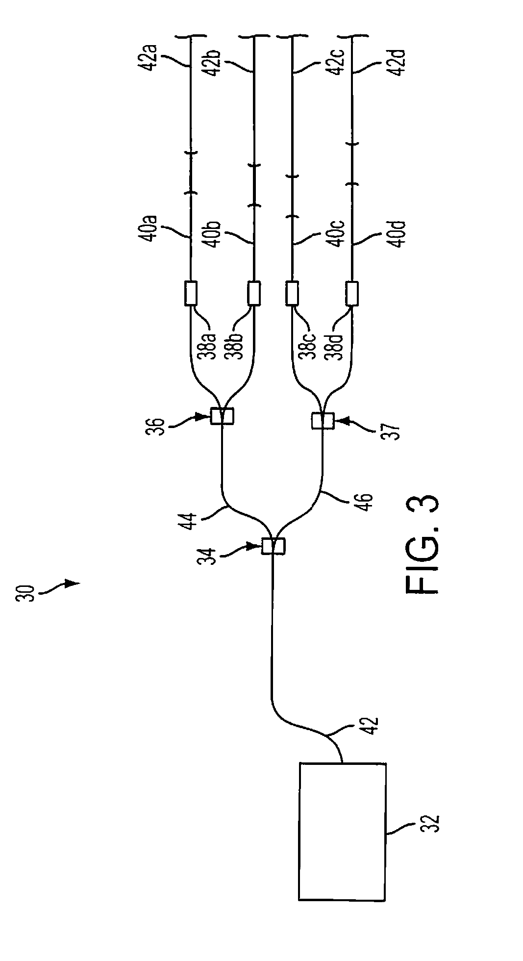
[0033] This example demonstrates the embodiment of FIG. 3, i.e., the four emitter, high brightness fiber source infrared simulator for hardware-in-the-loop simulation system.

[0034] Laser 32 was a 5 watt commercially available pump laser operating at 2 μm. The output fiber 42 from the laser was fusion spliced to a 1×2 50 / 50 splitter 34 operating at a wavelength of 2 μm. The arms 44,46 of splitter 34 were fusion spliced to two similar 1×2 splitters 36,37, effectively dividing the output pump light into four individual and equal power channels 40(a)-(d), which were standard silica fibers SMF-28. The outputs of the final chain of the 1×2 splitters were fusion spliced to fiber optic variable optical attenuators 38(a)-(d). The variable optical attenuators act as attenuators and modulators in each channel to control the pump light power and temporal characteristics. Each variable optical attenuator was capable of about 30 dB dynamic range and about 15 ms temporal response for modulation. ...

example 2

[0035] This example demonstrates the embodiment of FIG. 5, which shows a schematic of a high resolution n×n infrared scene simulator based upon the fiber technology. Here, each channel was coupled to each element of an n×n fiber array (n×n=N total elements) which was used to project a scene with a resolution of n×n pixels. The fiber array was constructed from a bundle of individual rare earth doped infrared fibers but can also be constructed from a rare earth doped glass extruded through a structured hole capillary plate with n×n holes.

example 3

[0036] This example shows the embodiment of FIG. 6, which shows a schematic of a of an alternate embodiment of the infrared fiber simulator. Here, a single infrared fiber source 62 is used. The infrared fiber source is split into n×n channels using a cascaded 1×2 chalcogenide 50 / 50 fiber coupler. The output of each coupler in the cascade is coupled to an infrared fiber based variable optical attenuator which controls the modulation and attenuation of each channel to achieve control of the temporal and spatial dynamics of the generated scene.

[0037] The use of rugged fiber optic components is a desirable advantage for these systems. Current resistor arrays systems are subject to pixel burnout, environmental aging and short life cycles and low yield during fabrication. As a result, commercially available resistor array scene projectors are very expensive to purchase and maintain. Also, they require external cooling resources and environmental resources to maintain their stability and ...


PUM

PropertyMeasurementUnit
core diametersaaaaaaaaaa
wavelengthaaaaaaaaaa

Abstract

This invention pertains to a scene projection system and a method for projecting a scene that can simulate light temperature of above 2000 K. The system comprises of a light source part for generating light at a lower wavelength; a means part for individually controlling dynamic range, contrast, brightness, temporal characteristics and temporal dynamics of the light; a rare earth doped fiber part that re-emits the output light at a higher wavelength; and a means part for conveying light between its parts. The method comprises steps of generating light at a lower wavelength wavelength; individually controlling temporal characteristics, temporal dynamics, brightness and contrast of the light; passing the light through a rare earth-doped fiber; and re-emitting the light at a higher wavelength.

Description

FIELD OF THE INVENTION [0001] This invention pertains to doped fiber projection system and method for projecting infrared scene, particularly for hardware-in-the-loop (HWIL) testing. DESCRIPTION OF RELATED PRIOR ART [0002] Hardware-in-the-loop simulation is used to test and evaluate seekers and electro-optic systems by projecting a synthetic environment to stimulate the system and evaluate the response of the system to the external synthetic environment. Hardware-in-the-loop testing offers great cost savings regarding field testing of these systems. Testing in simulators also removes many unknown variables inherent in field tests and allows careful control of the testing variables for complete characterization of the electro-optic system. Current hardware-in-the-loop simulation systems are often based upon resistor array technologies. In these systems, the synthetic infrared scene is generated through controlled heating of the tiny resistive emitters on the array. Due to the resisti...

Claims


Application Information

Patent Timeline
Patent Type & Authority Applications(United States)
IPC IPC(8): H01S3/30G02F1/35
CPCF41G7/00F41G7/004G01S3/7803H01S3/067H01S3/06754H01S3/094061H01S3/1022H01S3/1603H01S3/1613H01S3/1616H01S3/2383H01S2303/00H04N9/31Y10S385/901
Inventor SHAW, BRANDONSANGTIERA, JASBINDER S.AGGARWAL, ISHWAR D.THIELEN, PETER A.
Owner THE UNITED STATES OF AMERICA AS REPRESENTED BY THE SECRETARY OF THE NAVY
Why Eureka
Try Eureka