
Apparatus and method for simulation of combustion effects in a fireplace

a technology of apparatus and methods, applied in the field of apparatus and methods for simulation of combustion effects in fireplaces, can solve the problems of complex devices, time-consuming and expensive manufacturing, and inability to simulate combustion effects, so as to improve the realism of the fire effect and the degree of transparency

Inactive Publication Date: 2007-06-07
GHP GRP
View PDF3 Cites 46 Cited by
  • Summary
  • Abstract
  • Description
  • Claims
  • Application Information

AI Technical Summary

Benefits of technology

[0015] An additional embodiment includes a screen or privacy glass panel, made of material that has a property of changing the opacity according to the electric current applied to it. The privacy glass panel has a high degree of transparency when electrical current is applied. A controller applies electrical current to the privacy glass when the fireplace is turned off. This allows the user to see through this glass and have the visual perception of the logs and ember bed when the fireplace is off. The privacy glass is cloudy or hazy when no electrical current is applied. A controller prevents the flow of electrical current to the privacy glass when the fireplace is turned on. The privacy glass can be positioned anywhere inside the fireplace—such as inside the ember-bed or imitation logs—because it is nearly invisible to the user when the fireplace unit is off.
[0016] More specifically, the privacy glass may be made from clear or tinted glass or a glass-like polymeric-based material, such as polycarbonates, through the use of which image of flickering flames is produced that is well defined and realistic. The material used for the privacy glass can be free-forming so that the glass can be manipulated into any shape desired. For example, forming the privacy glass to a three-dimensional shape can create the look of a flame that would appear to be coming from different planes within the ember-bed and / or logs, greatly improving the realism of the fire effect in the electric fireplaces.
[0019] One embodiment of the refractories includes a surface having at least one face on the surface, to allow refraction of light in more than one direction. This allows the simulation of a glowing ember bed effect to be viewed from more than one angle from the front of the fireplace. The refractories may include a surface having a plurality of faces positioned around the surface so that light is refracted in a multiple of directions thereby assisting in the ember bed simulation. The refractories may be one single multifaceted bead or a plurality of beads to realistically replicate real bed embers. Refractories that are suitable for this purpose include multifaceted beads made from plastic, glass, or a naturally occurring material; broken pieces of tempered glass; and broken pieces of plastic such as acrylic or polycarbonate may be used as refractories. The refractories may be clear or colored including those that are, for example painted with stained glass paint.
[0021] Another preferred embodiment of the present invention uses light emitting diodes, termed LEDs for some or all illumination purposes. A light emitting diode is any semiconductor device that emits visible light when an electric current is passed through it. LEDs can be of varying type such as air gap LEDs, GaAs LEDs and polymer LEDs. LEDs are high intensity, energy efficient illumination sources. LEDs, either individually or custom packaged, are commercially available. LEDs produce light in many colors, including, but not limited to, amber, yellow, orange, green, blue and white—further, an individual LED may be designed to change colors, varying from amber to yellow to orange, in response to an electrical signal. LEDs give off virtually no heat and have a relatively unlimited lifetime, essentially eliminating the need for replacement. The LEDs may comprise a plurality, or cluster, of LEDs. Alternatively, the LEDs may comprise one individual LED. Again, the intensity of the light source may be varied such as by varying the location and / or number of LEDs. Further, the LEDs can include a textured surface to provide “diffused light”. “Sandblasting” provides such a textured surface.
[0022] Illumination in other embodiments of the present invention may be provided by one or more long-life halogen light bulbs, incandescent light bulbs, flame based sources, carbon arc radiation sources, fluorescent sources, luminescent bulbs or induction light bulbs. Some embodiments of the present invention contemplate a combination of LEDs and non-LED sources of light as will be detailed below. Fiber optic cables, or any other material that facilitates the transmission of light, such as acrylic or nylon, may be used to assist in transmitting the visible light form source to a point of illumination and ultimately, a viewer.

Problems solved by technology

However, depending on the geographical region in which the fireplace is used, gas may be an expensive source of energy.
However, electric fireplaces do not have the same combustion effects that are produced by fuel burning fireplaces.
In general, these efforts have produced devices that are complex, multi-component arrangements that are time-consuming and expensive to manufacture.
Also, the flame, burning logs and ember bed effect simulated by the devices has been generally limited in scope.
With time, consumers find the simulation unconvincing representations of actual combustion effects.
Drawbacks include unrealistic flame appearance and repetition of the flame simulation over a short period of time.
An additional disadvantage is that the effect relies on the use of a motor to rotate the light randomizer.
Also, the life of a standard light bulb is short and therefore must be frequently replaced.
This approach is complicated since it is highly dependent upon accurate placement of many reflecting surfaces.
An additional drawback of this method is that the embers glow unrealistically since real glowing embers tend to pulse in color and intensity—from low to high intensity and back—depending on the air flow around them.

Method used


Image

  • Apparatus and method for simulation of combustion effects in a fireplace
  • Apparatus and method for simulation of combustion effects in a fireplace
  • Apparatus and method for simulation of combustion effects in a fireplace

Examples


Embodiment Construction

[0031] The present invention will now be described in detail with reference to certain embodiments thereof as illustrated in the accompanying drawings. In the following description, numerous specific details are set forth in order to provide a thorough understanding of the present invention. It will be apparent, however, to one skilled in the art, that the present invention may be practiced without some or all of these specific details. In other instances, well-known process steps and / or structures have not been described in detail to prevent unnecessarily obscuring the present invention.

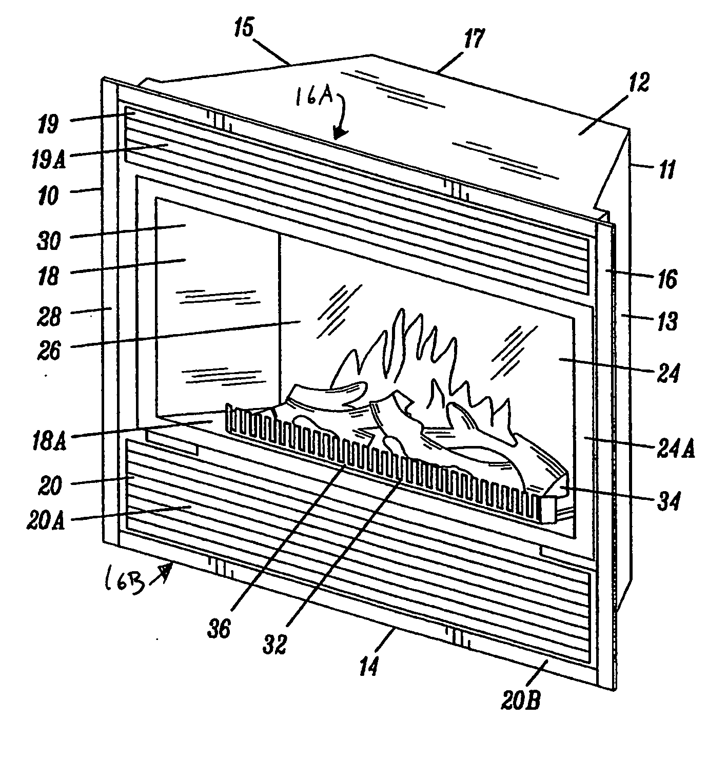
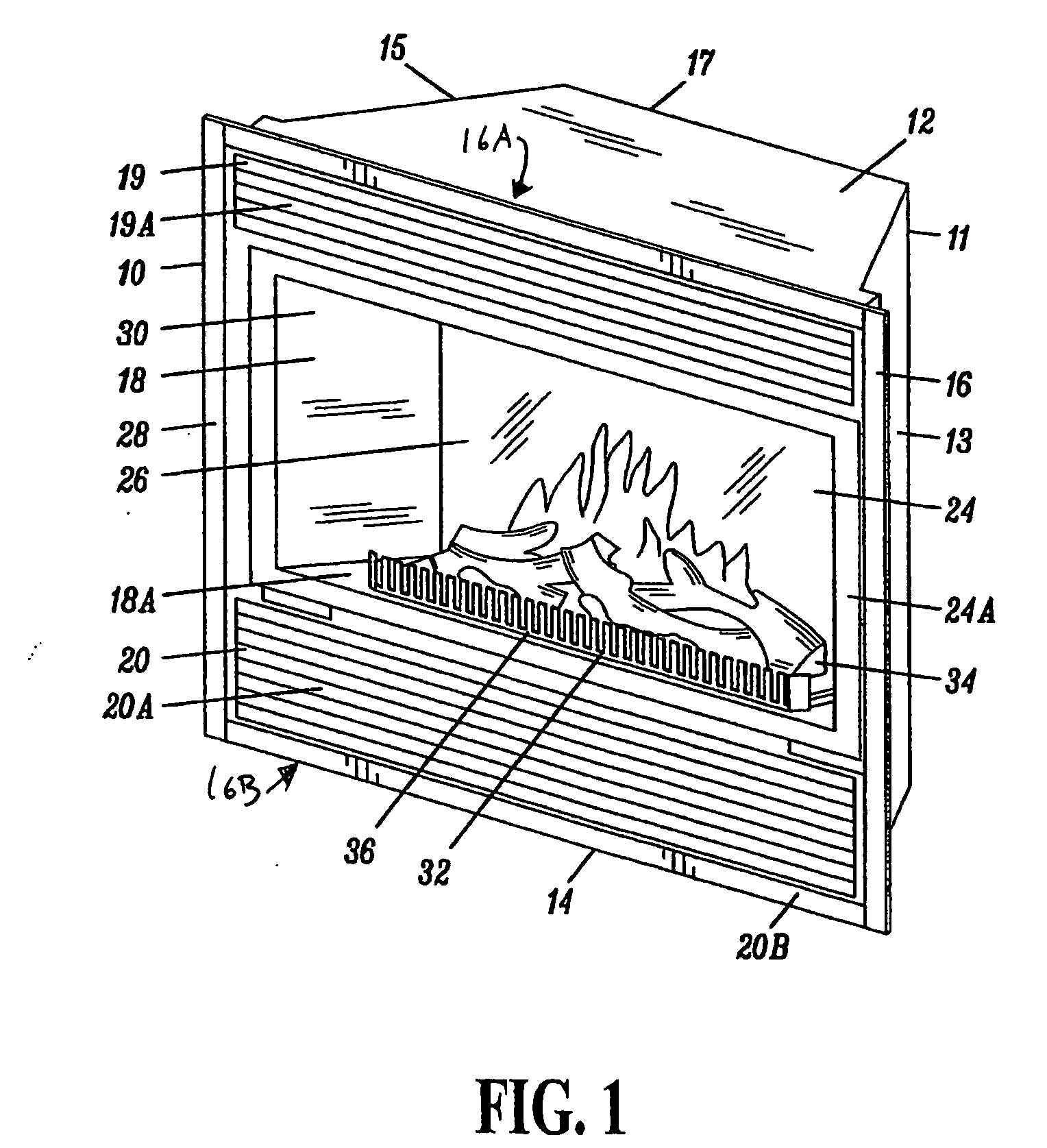
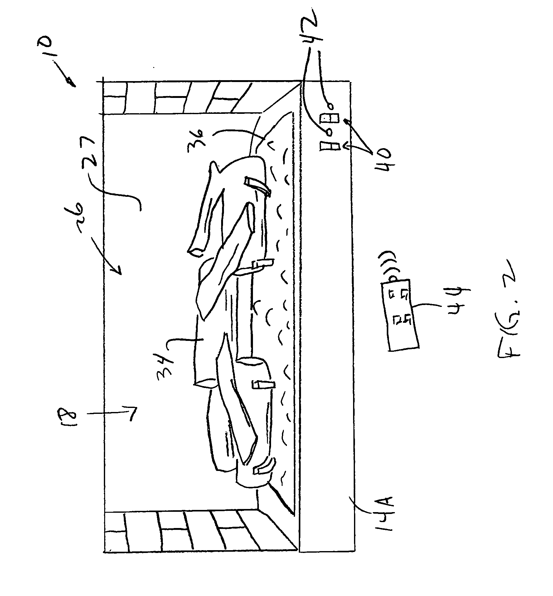
[0032] The present invention is used as an electric fireplace 10. The assembly of one type of electric fireplace 10 that is the subject of the present invention is illustrated in FIG. 1. This embodiment of fireplace 10 includes a housing 11 having a top panel 12, a bottom panel 14, two opposing side panels 13 and 15, a front side 16, and a back panel 17 that collectively generally define an interio...


PUM


Abstract

The present invention produces a combustion simulation of flames, burning logs and embers in a fuel-burning fireplace or like device. One or more light source(s), such as LEDs, are used to transmit light to and through one or more of an artificial log set and an ember bed. A microprocessor-based controller is used to vary one or more of light intensity and color of the LEDs to simulate a naturally varying glow effect of the ember bed and the log set.

Description

[0001] This application claims benefit of U.S. Provisional Application No. 60 / 700,755, filed Jul. 19, 2005.FIELD OF THE INVENTION [0002] The present invention relates generally to electric fireplace technology. In particular, the present invention relates to an apparatus and methods that provide improved simulation of combustion effects in a fireplace through illumination. BACKGROUND OF THE INVENTION [0003] Fireplaces are desirable features in the home. Traditional wood or other solid fuel burning fireplaces have, however, gradually become replaced by devices that burn non-solid materials, such as gas, or that produce heat electrically. The combustion of gas does provide real flames and heat. However, depending on the geographical region in which the fireplace is used, gas may be an expensive source of energy. Gas combustion also requires a working flue to vent the combustion products. [0004] Electric or electronic fireplaces are a clean and easy source of heat. Electric fireplaces ...

Claims


Application Information

Patent Timeline
Patent Type & Authority Applications(United States)
IPC IPC(8): F24B1/193H05B44/00
CPCF24C7/004F24F2011/0091F24F11/52
Inventor LIM, ALVINLAURIE, JANEDONG, ZHENXINGJAMIESON, DONALD R.NADEN, DAMIR
Owner GHP GRP
Learn More