
Circulating fluidized bed boiler having improved reactant utilization

a technology of reactant utilization and fluidized bed, which is applied in the direction of lighting and heating apparatus, combustion types, furnaces, etc., can solve the problems of unacceptably high sulfur dioxide content of combustion product gas, unfavorable tree damage, and undesirable acid rain, so as to reduce the emission, and improve the utilization rate of reactan

Inactive Publication Date: 2007-05-31
THE POWER IND GRP
View PDF9 Cites 11 Cited by
  • Summary
  • Abstract
  • Description
  • Claims
  • Application Information

AI Technical Summary

Benefits of technology

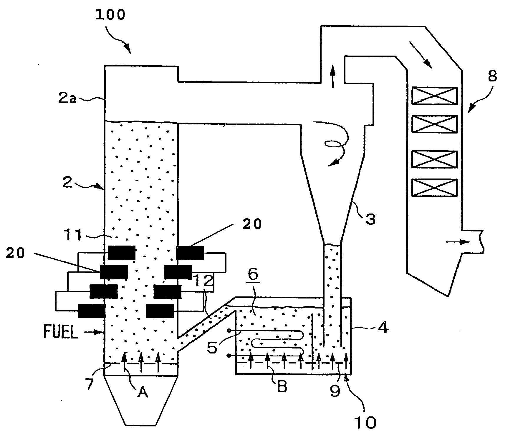
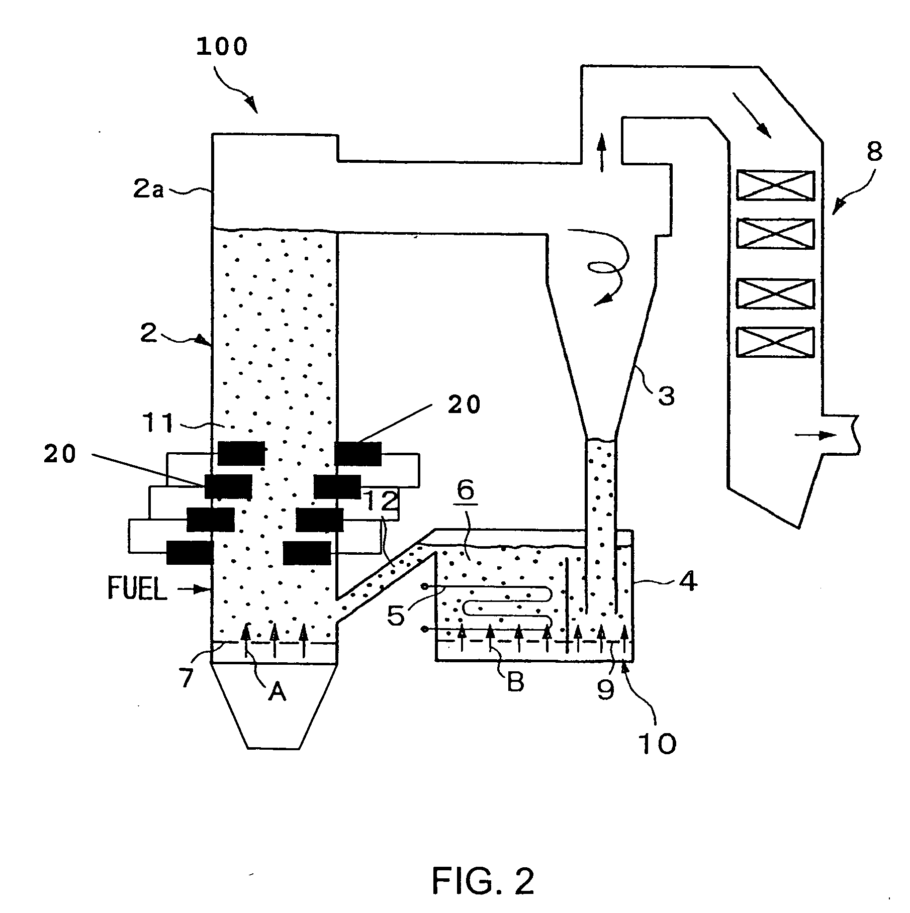
[0009] The present invention is directed to a circulating fluidized bed boiler having improved reactant utilization. The circulating fluidized bed boiler may include a circulating fluidized bed. The circulating fluidized bed may include a dense bed portion, a lower furnace portion adjacent to the dense bed portion, and an upper furnace portion. The dense bed portion of the circulating fluidized bed boiler is preferably maintained below the stoichiometric ratio (fuel rich stage) and the lower furnace portion is preferably maintained above the stoichiometric ratio (fuel lean stage), thereby reducing the formation of NOx. The circulating fluidized bed boiler may also include a reactant to reduce the emission of at least one combustion product in the flue gas, a plurality of secondary air injection ports downstream of the circulating fluidized bed for providing mixing of the reactant and the flue gas in the furnace above the dense bed, wherein the amount of reactant required for the reduction of the emission of the combustion product is reduced, and a return system for returning carry over particles from the flue gas to the circulating fluidized bed.
[0014] Accordingly, one aspect of the present invention is to provide a circulating fluidized bed boiler having improved reactant utilization. The circulating fluidized bed boiler includes: (a) a circulating fluidized bed including: a dense bed portion; a lower furnace portion adjacent to the dense bed portion; and an upper furnace portion; (b) a reactant to reduce the emission of at least one combustion product in the flue gas; and (c) a plurality of secondary air injection ports downstream of the circulating fluidized bed for providing mixing of the reactant and the flue gas in the furnace above the dense bed, wherein the amount of reactant required for the reduction of the emission of the combustion product is reduced.
[0015] Another aspect of the present invention is to provide a circulating fluidized bed boiler having improved reactant utilization. The circulating fluidized bed boiler includes: (a) a circulating fluidized bed including a dense bed portion, a lower furnace portion adjacent to the dense bed portion, and an upper furnace portion, wherein the dense bed portion of the circulating fluidized bed boiler is maintained below the stoichiometric ratio (fuel rich stage) and the lower furnace portion is maintained above the stoichiometric ratio (fuel lean stage), thereby reducing the formation of NOx; (b) a reactant to reduce the emission of at least one combustion product in the flue gas; and (c) a plurality of secondary air injection ports downstream of the circulating fluidized bed for providing mixing of the reactant and the flue gas in the furnace above the dense bed, wherein the amount of reactant required for the reduction of the emission of the combustion product is reduced.
[0016] Still another aspect of the present invention is to provide a circulating fluidized bed boiler having improved reactant utilization. The circulating fluidized bed boiler includes: (a) a circulating fluidized bed including: a dense bed portion; a lower furnace portion adjacent to the dense bed portion; and an upper furnace portion, wherein the dense bed portion of the circulating fluidized bed boiler is maintained below the stoichiometric ratio (fuel rich stage) and the lower furnace portion is maintained above the stoichiometric ratio (fuel lean stage), thereby reducing the formation of NOx; (b) a reactant to reduce the emission of at least one combustion product in the flue gas; (c) a plurality of secondary air injection ports downstream of the circulating fluidized bed for providing mixing of the reactant and the flue gas in the furnace above the dense bed, wherein the amount of reactant required for the reduction of the emission of the combustion product is reduced; and (d) a return system for returning carry over particles from the flue gas to the circulating fluidized bed.

Problems solved by technology

The combustion of sulfur-containing carbonaceous compounds, especially coal, results in a combustion product gas containing unacceptably high levels of sulfur dioxide.
Atmospheric SO2 or H2SO4 results in undesirable “acid rain.”
According to the U.S. Environmental Protection Agency, acid rain causes acidification of lakes and streams and contributes to damage of trees at high elevations and many sensitive forest soils.
In addition, acid rain accelerates the decay of building materials and paints, including irreplaceable buildings, statues, and sculptures.
Prior to falling to the earth, SO2 and NOx gases and their particulate matter derivatives, sulfates and nitrates, also contribute to visibility degradation and harm public health.
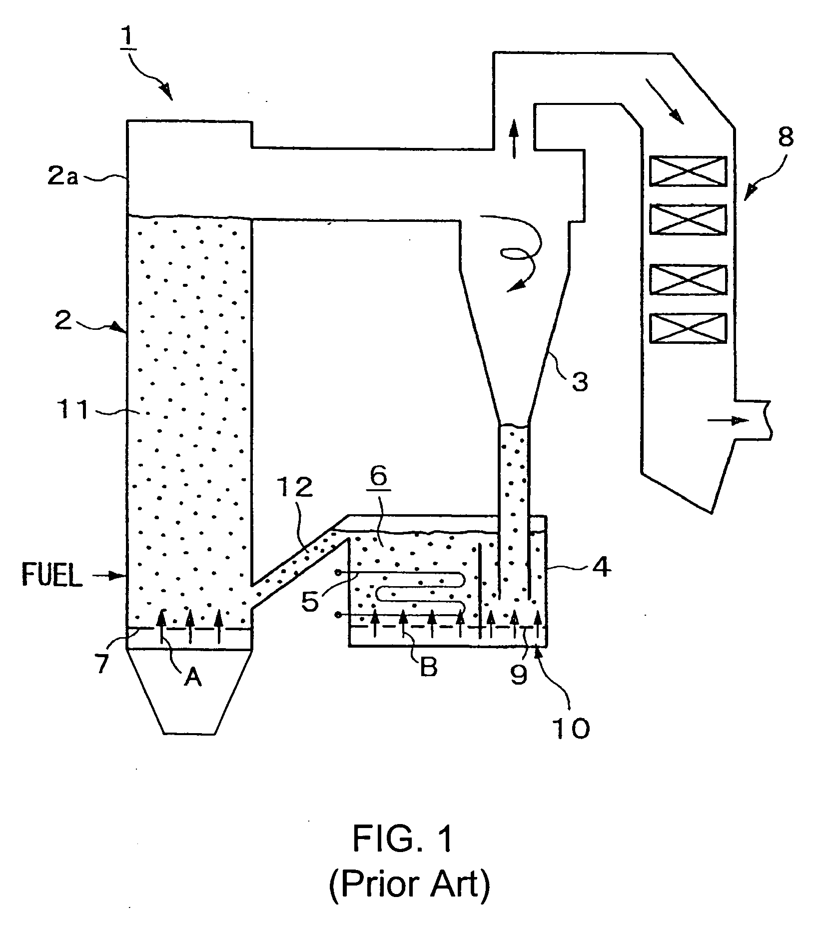
However, due to inefficient mixing, the ratio often increases to 3.0 or more to achieve desired levels of SO2 capture.
The higher ratio of Ca / S requires more limestone to be utilized in the process, thereby increasing operating costs.
Additionally, inefficient mixing results in the formation of combustion “hotspots” that promote the formation of NOx.

Method used


Image

  • Circulating fluidized bed boiler having improved reactant utilization
  • Circulating fluidized bed boiler having improved reactant utilization
  • Circulating fluidized bed boiler having improved reactant utilization

Examples


example 1

[0044] FLUENT, a computational fluid dynamics analytic software program available from Fluent, Inc. of Lebanon, N.H., was used to model two-phase thermo-fluid phenomena in a CFB power plant. FLUENT solves for the velocity, temperature, and species concentrations fields for gas and particles in the furnace. Since the volume fraction of particle phase in a CFB is typically between about 0.1% and 0.3%, a granular model solving multi-phase flow was applied to this case. In contrast to conventional pulverized-fuel combustion models, where the particle phase is solved by a discrete phase model in a granular model both gas phase and particle phase conservation equations are solved in an Eulerian reference frame.

[0045] The solved conservation equations included continuity, momentum, turbulence, and enthalpy for each phase. In this multi-phase model, the gas phase (>99.7% of the volume) is the primary phase, while the particle phases with its individual size and / or particle type are modeled...


PUM


Abstract

A circulating fluidized bed boiler having improved reactant utilization. The circulating fluidized bed boiler includes a circulating fluidized bed having a dense bed portion; a lower furnace portion adjacent to the dense bed portion; and an upper furnace portion, wherein the dense bed portion of the circulating fluidized bed boiler is maintained below the stoichiometric ratio (fuel rich stage) and the lower furnace portion is maintained above the stoichiometric ratio (fuel lean stage), thereby reducing the formation of NOx.; a reactant to reduce the emission of at least one combustion product in the flue gas; and a plurality of secondary air injection ports downstream of the circulating fluidized bed for providing mixing of the reactant and the flue gas in the furnace above the dense bed, wherein the amount of reactant required for the reduction of the emission of the combustion product is reduced. In a preferred embodiment, the circulating fluidized bed boiler may further include a return system for returning carry over particles from the flue gas to the circulating fluidized bed.

Description

BACKGROUND OF THE INVENTION [0001] (1) Field of the Invention [0002] The present invention relates generally to a circulating fluidized bed boilers and, more particularly to a circulating fluidized bed boiler having improved reactant utilization for reduction of undesirable combustion products. [0003] (2) Description of the Prior Art [0004] The combustion of sulfur-containing carbonaceous compounds, especially coal, results in a combustion product gas containing unacceptably high levels of sulfur dioxide. Sulfur dioxide is a colorless gas, which is moderately soluble in water and aqueous liquids. It is formed primarily during the combustion of sulfur-containing fuel or waste. Once released to the atmosphere, sulfur dioxide reacts slowly to form sulfuric acid (H2SO4), inorganic sulfate compounds, and organic sulfate compounds. Atmospheric SO2 or H2SO4 results in undesirable “acid rain.”[0005] According to the U.S. Environmental Protection Agency, acid rain causes acidification of lak...

Claims


Application Information

Patent Timeline
Patent Type & Authority Applications(United States)
IPC IPC(8): F23C10/00
CPCF23C10/10F23C2206/103F23J7/00F23C10/00
Inventor HIGGINS, BRIAN S.
Owner THE POWER IND GRP
Learn More