
Front structure for vehicle

a front structure and vehicle technology, applied in the direction of roofs, bumpers, cycles, etc., can solve the problem of restricting the arrangement of the grip portions used in the movement of the vehicle, and achieve the effect of preventing the coming in of mud, and reducing the risk of accidents

Inactive Publication Date: 2007-05-24
HONDA MOTOR CO LTD
View PDF8 Cites 6 Cited by
  • Summary
  • Abstract
  • Description
  • Claims
  • Application Information

AI Technical Summary

Benefits of technology

[0007] One or more embodiments of the present invention provide a front structure for a vehicle having a carry pipe excellent in appearance quality, capable of restraining the coming-in of mud, water or the like due to mud splashes during running, and capable of being gripped easily.
[0009] In the front structure, the grille covers from the front side the vertical-direction extension portions of the carry pipe, while exposing at least a part of the left-right direction extension portions, and the extension wall portions of the light units are disposed so as to overlap with the grille. Therefore, the front structure for a vehicle is good in appearance quality, and the gap between the grille and the vehicle body side can be eliminated, whereby it is made difficult for mud, water and he like splashed during running to enter to the vehicle body side. Further, since the left-right direction extension portions of the carry pipe are not covered by other members, the carry pipe can be gripped easily, promising an excellent operability.
[0011] When the front structure is provided with: the radiator disposed on the rear side of the grille; and the shroud extending in the front-rear direction on lateral sides of the radiator, and the lap areas where the grille and the extension wall portions of the light units overlap are located on the front side of the shroud, a duct is formed by the grille and the extension wall portions of the light units. As a result, the outside air is efficiently guided to the shroud, and air intake is achieved easily. Further, it is made difficult for mud, water and the like to enter to the vehicle body side during running.
[0013] When the grille has a flange portion so formed as to surround the left-right direction extension portions of the carry pipe, and the flange portion overlaps with the extension wall portions of the light units, the gap between the grille and the vehicle body side can be eliminated. Therefore, it is made difficult for mud, water and the like to enter to the vehicle body side, and appearance quality is enhanced.
[0015] When the extension wall portions of the light units extend along the left-right direction extension portions of the carry pipe, the rear side of the left-right direction extension portions of the carry pipe can be covered. As a result, the mud, water and the like due to mud splashes are received by the extension wall portions and, hence, would not easily enter to the vehicle body side, and appearance quality can be enhanced.
[0017] When the carry pipe has a plurality of left-right direction extension portions in the left-right direction, and tip end portions of at least one pair of left-right direction extension portions are connected to each other, easily grippable portions of the carry pipe can be gripped according to the situation, whereby operability is enhanced.

Problems solved by technology

In this case, there is a limitation to the arrangement in which the grip portions to be used in moving the vehicle are provided at lower positions in the vehicle body.

Method used


Image

  • Front structure for vehicle
  • Front structure for vehicle
  • Front structure for vehicle

Examples


Embodiment Construction

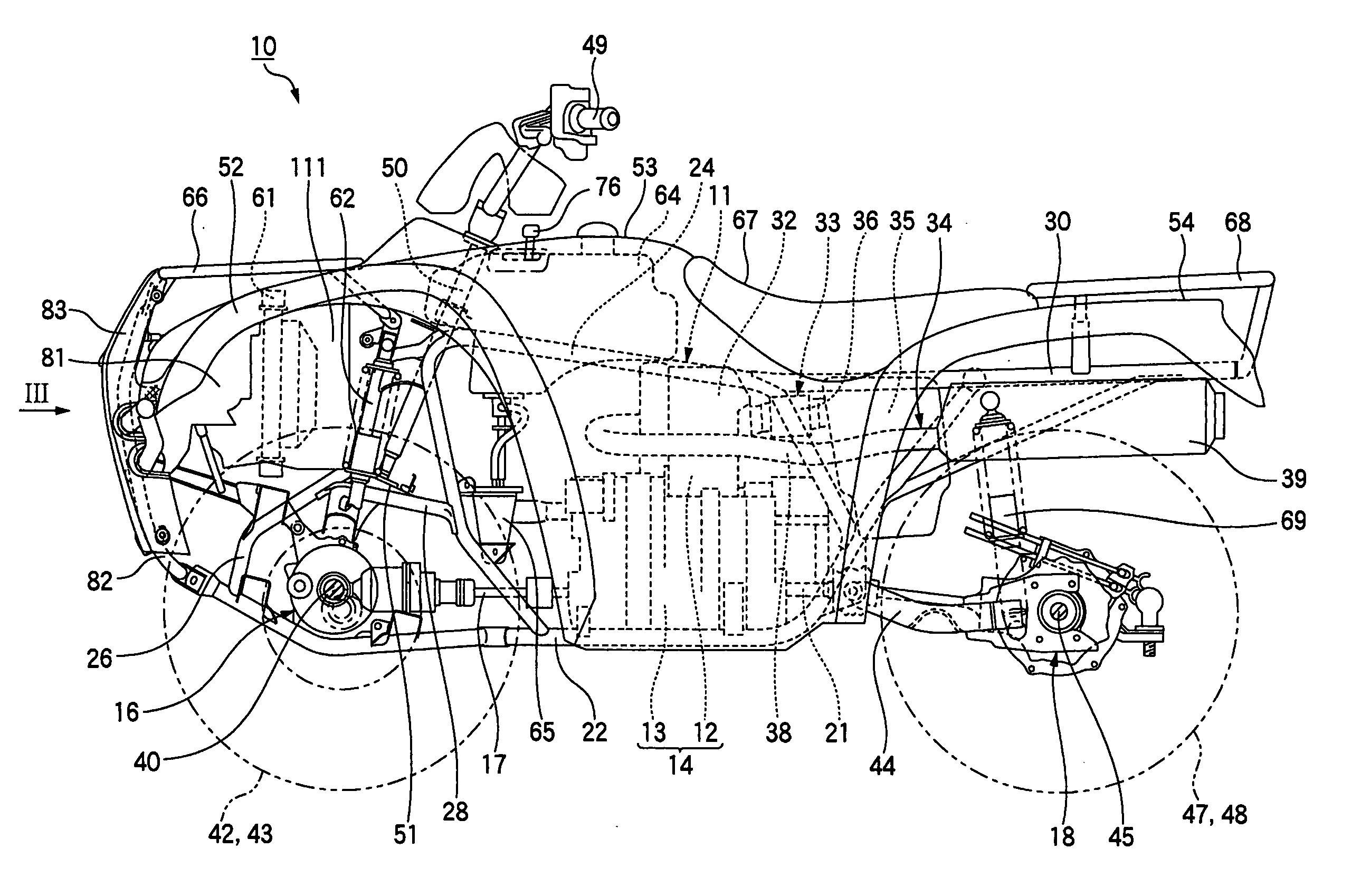
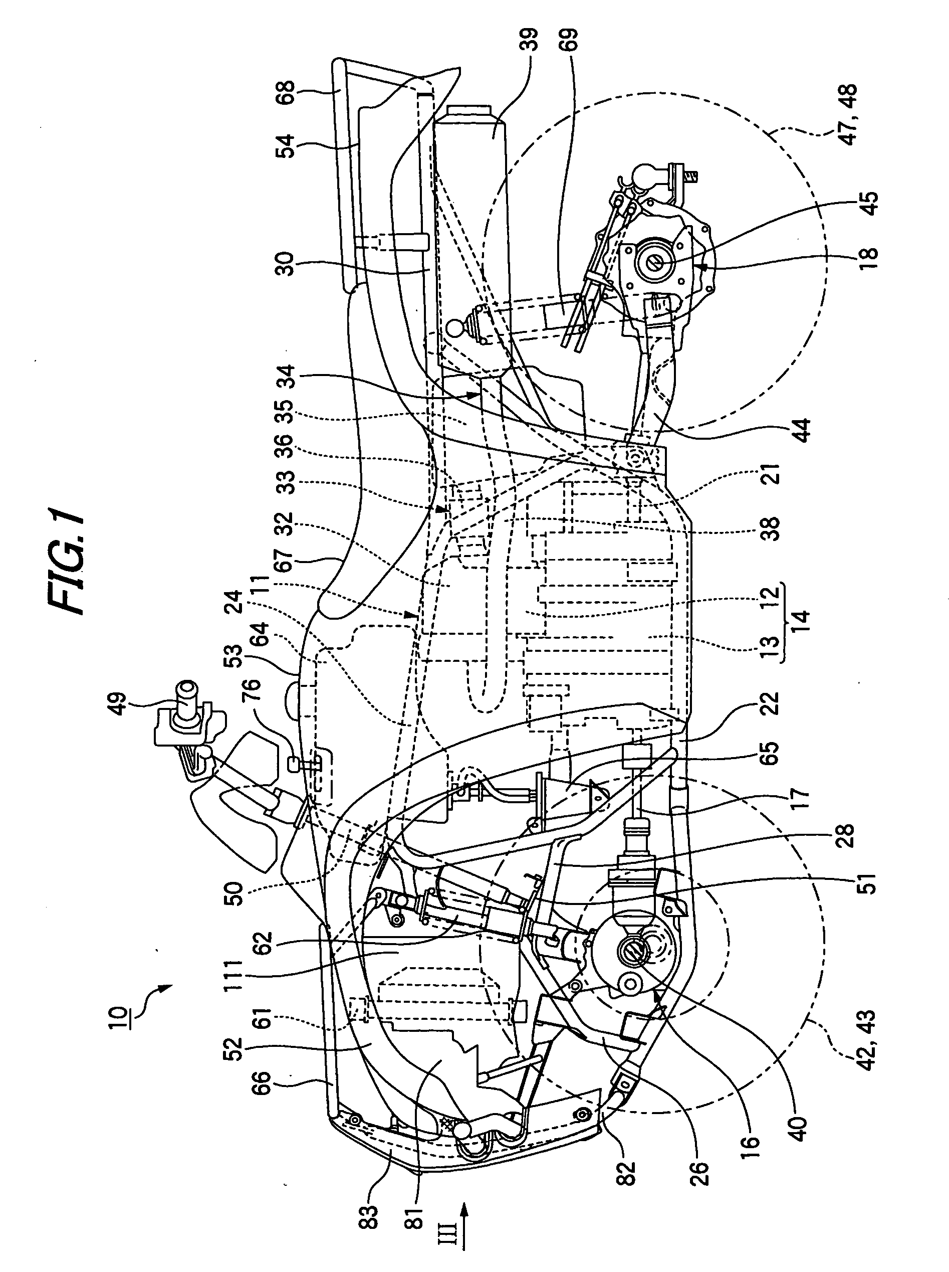
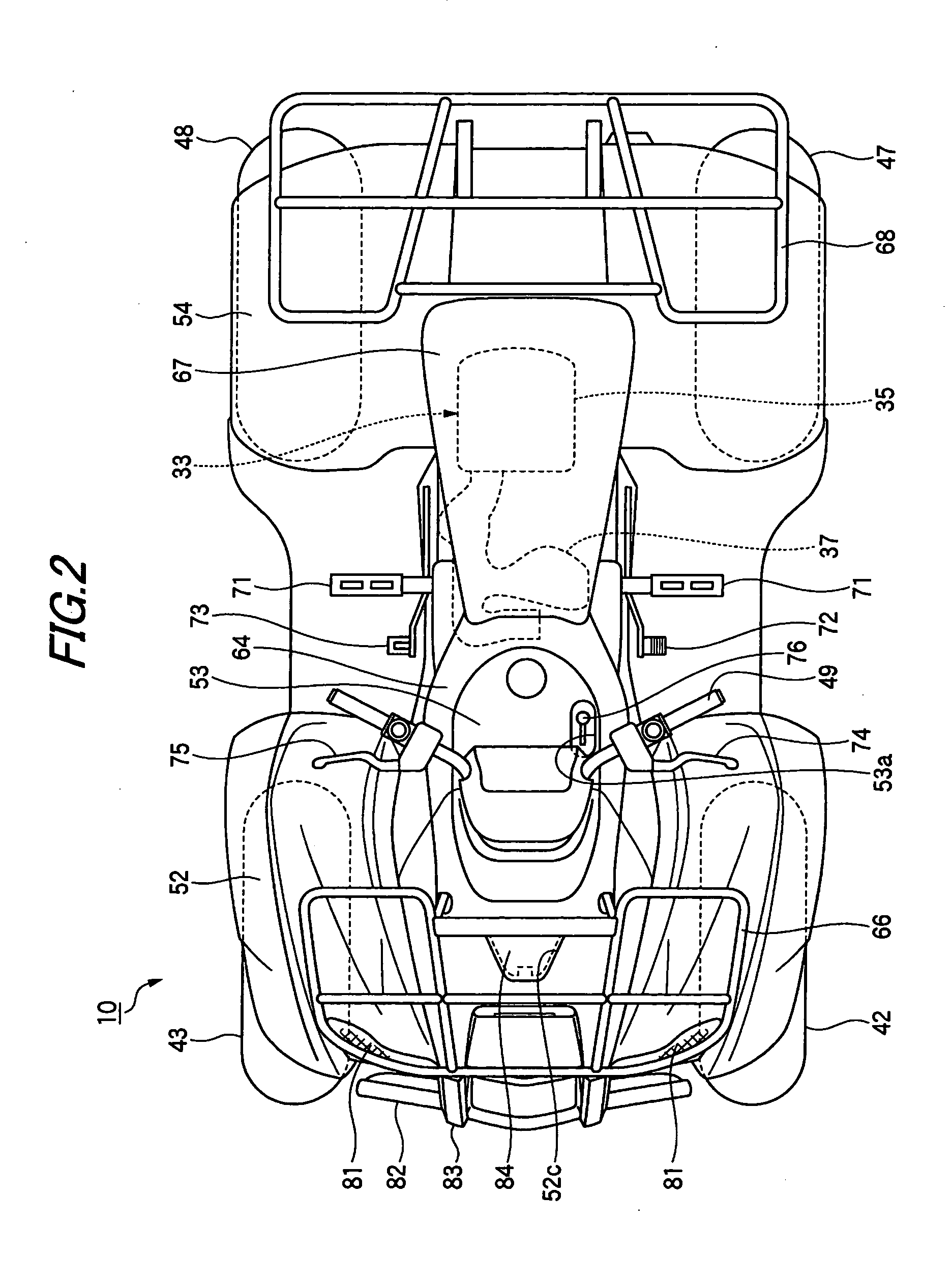
[0032] An exemplary embodiment of the invention will be described with reference to the accompanying drawings. Incidentally, the drawings are to be looked at according to the posture of symbols. FIG. 1 is a side view of a vehicle configured by adopting a front structure for a vehicle according to the exemplary embodiment of present invention, and FIG. 2 is a plan view of the vehicle.

[0033] First, the general structure of the vehicle 10 will be described, based on FIGS. 1 and 2. As shown in FIGS. 1 and 2, the vehicle 10 is a four-wheel-drive type all-terrain vehicle (ATV) in which a power unit 14 composed of a longitudinally disposed engine 12 and a transmission 13 is disposed substantially at the center of a vehicle body frame 11, a front final assembly 16 disposed on the front side of the power unit 14 and the transmission 13 are connected to each other through a front propeller shaft 17, and a rear final assembly 18 disposed on the rear side of the power unit 14 and the transmiss...


PUM


Abstract

A front structure for a vehicle is provided with a vehicle body frame, a front cover covering a front portion of the vehicle body frame, a left-right pair of light units supported on the front cover, a carry pipe supported at the front end of the vehicle body frame, and a grille disposed on the front side of the carry pipe. The carry pipe is provided with a vertical-direction extension portion and a left-right direction extension portion. The grille covers the vertical-direction extension portion from the front side while exposing at least a part of the left-right direction extension portion. Each of the light units has a front extension wall portion overlapping with a flange portion of the grille.

Description

[0001] This application claims foreign priority from Japanese Patent Application No. 2005-334432, filed on Nov. 18, 2005, the entire contents of which are hereby incorporated by reference. BACKGROUND OF THE INVENTION [0002] 1. Field of the Invention [0003] The present invention relates to a front structure for a vehicle such as an all-terrain vehicle. [0004] 2. Related Art [0005] As a conventional all-terrain vehicle, there has been known a vehicle front structure comprising light units, a carry pipe, a front grille and the like on the vehicle body front side (refer to, for example, JP-A-2005-104282). The front structure described in JP-A-2005-104282 has a configuration in which the vertical direction of a front surface of the carry pipe is covered with the front grille, and grip portions provided to extend sideways from the carry pipe are covered with a cover disposed to surround edge portions of the light units. [0006] Meanwhile, according to the front structure described in JP-A-...

Claims


Application Information

Patent Timeline
Patent Type & Authority Applications(United States)
IPC IPC(8): B62D25/08B60Q1/04B60R19/02B60R19/52B62K5/00B62K5/01
CPCB62K5/01
Inventor ICHIKAWA, MANABU
Owner HONDA MOTOR CO LTD
Learn More