
Hardfacing materials with highly conforming properties

a hardfacing material and conforming technology, applied in the field of drill bits, can solve the problems of welded inner parts, time-consuming and expensive machining, and inability to meet the requirements of the material, and achieve the effect of increasing the durability of the drill bi

Inactive Publication Date: 2007-05-17
BAKER HUGHES INC
View PDF11 Cites 38 Cited by
  • Summary
  • Abstract
  • Description
  • Claims
  • Application Information

AI Technical Summary

Benefits of technology

[0008] A method of increasing the durability of a drill bit, which includes the step providing a pliable sheet of a hardfacing matrix material. The pliable sheet of hardfacing material has a nickel and chromium matrix combined with a first element. The first element is selected from a group consisting of spherical sintered tungsten carbide, spherical cast tungsten carbide, and metallic glass. The hardfacing matrix material sheet is placed on a preselected surface of the drill bit. The hardfacing matrix material sheet is then fusion bonded to the drill bit.
[0012] A method of increasing the durability of a drag bit type of drill bit, when the drag bit has a plurality of blades and a slot formed between each pair of adjacent blades. Each of the blades have a cutting region with cutting elements and a gage surface free of cutting elements. The method includes the step of providing a sheet of a hardfacing matrix material comprising a nickel and chromium matrix combined with a first element selected from a group consisting of spherical sintered tungsten carbide, spherical cast tungsten carbide, and metallic glass. The sheet of a hardfacing matrix material is cut into a pattern corresponding to a preselected surface of the drag bit. The pattern is adhered to the preselected surface of the drag bit. The drill bit, with the pattern adhered thereto is heated in order to bond the pattern to the drag bit.

Problems solved by technology

Even with skilled welders, imperfections can be present due to varying thicknesses of the weld, shape of the drill bit the hardfacing is being welded upon, and the beads associated with welding processes.
Machining can be time-consuming and expensive.
Moreover, hardfacing was not welded to inner parts due to narrow clearances and expense.

Method used


Image

  • Hardfacing materials with highly conforming properties
  • Hardfacing materials with highly conforming properties
  • Hardfacing materials with highly conforming properties

Examples


Embodiment Construction

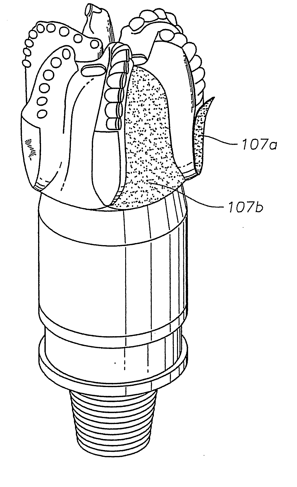
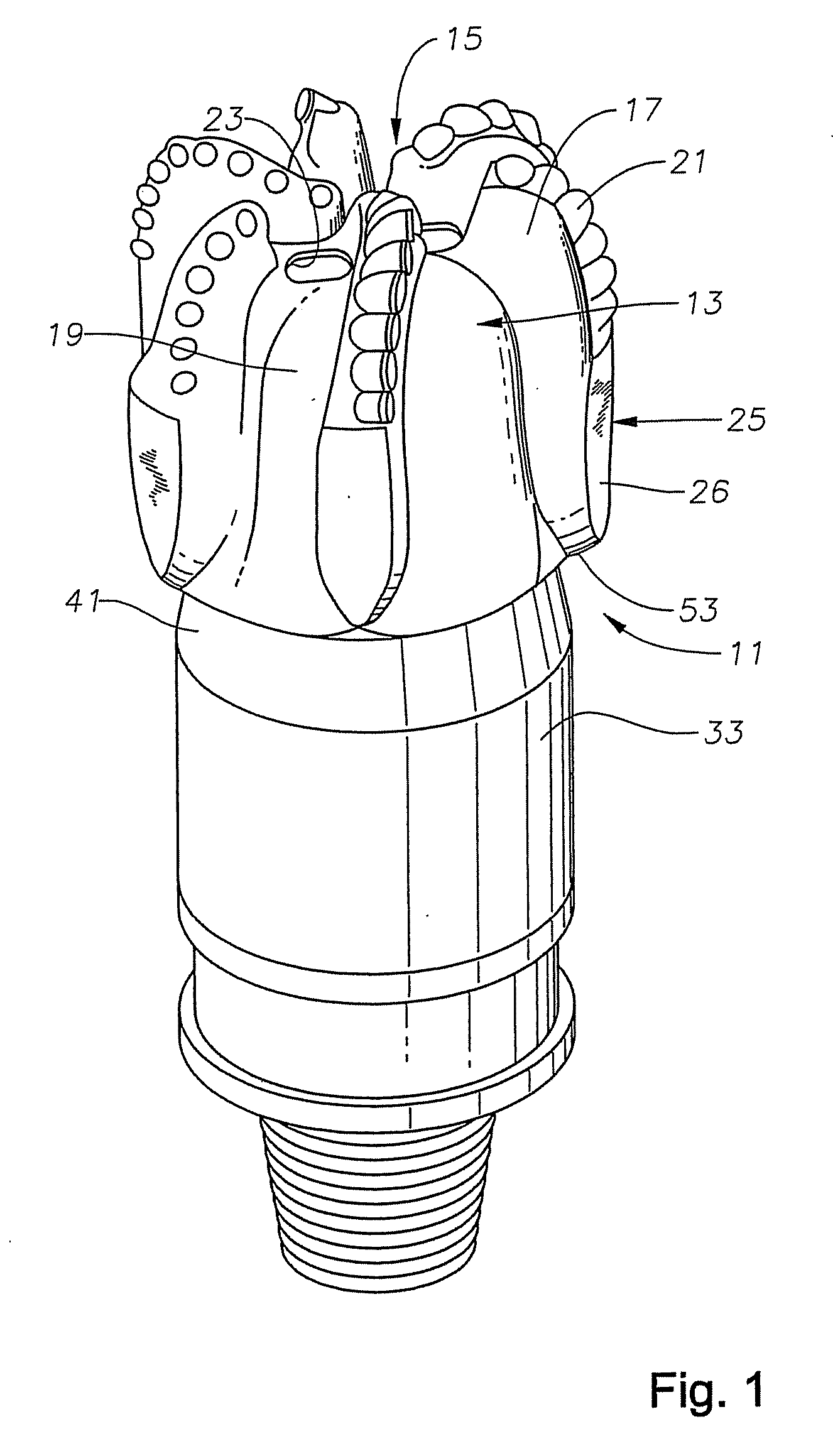
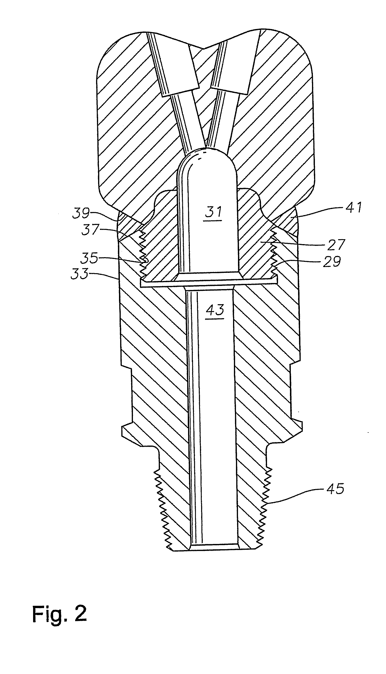
[0024] Referring to FIG. 1, bit assembly 11 has a body 13 on a lower end. Body 13 has a face 15 on its lower end. A plurality of blades 17 are formed on and protrude from face 15, with six blades 17 being shown in the drawings. Blades 17 lead outward from a central portion of face 15 to a gage area at the periphery of body 13. Blades 17 are separated from each other, defining junk slots 19 between them for the passage of drilling fluid and cuttings. Each blade 17 contains a row of conventional cutters typically polycrystalline diamond (PCD). Nozzles 23 discharge drilling fluid, which flows through junk slots 19 and back up the borehole along with the cuttings. While bit assembly 11 is illustrated as a “drag bit” or steel-bodied bit, it should be readily apparent to those skilled in the art that the teachings herein are also applicable to tri-cone bits, or cast bits, such as those illustrated in FIG. 1 of U.S. Reissue Pat. No. RE 37,127.

[0025] A set of primary gage pads 25 is integr...


PUM

PropertyMeasurementUnit
durabilityaaaaaaaaaa
metallicaaaaaaaaaa
areaaaaaaaaaaa

Abstract

An earth-boring bit, and a method of increasing the durability of the same, which includes the step providing a pliable sheet of a hardfacing matrix material. The pliable sheet of hardfacing material has a nickel and chromium matrix combined with a first element. The first element is selected from a group consisting of spherical sintered tungsten carbide, spherical cast tungsten carbide, and metallic glass. The hardfacing matrix material sheet is placed on a preselected surface of the drill bit. The hardfacing matrix material sheet is then fusion bonded to the drill bit.

Description

RELATED APPLICATIONS [0001] This nonprovisional patent application claims the benefit of co-pending, provisional patent application U.S. Ser. No. 60 / 737,003, filed on Nov. 15, 2005, which is hereby incorporated by reference in its entirety.BACKGROUND OF THE INVENTION [0002] 1. Field of the Invention [0003] This invention relates in general to drill bits for well drilling, and in particular to a metallic hardfacing matrix and method of applying the metallic hardfacing matrix to drill bits. [0004] 2. Background of the Invention [0005] Rotary well drilling for oil and gas is primarily accomplished through one of two types of bits. In a rotary cutter bit, the bit body has typically three rotatable cones or cutters. The cones rotate on bearing pins and have teeth or tungsten carbide inserts for disintegrating the earth formation. In the fixed cutter or drag bit type, the bit body has a face which contains cutting elements mounted on fixed blades. The cutting elements are typically polycr...

Claims


Application Information

Patent Timeline
Patent Type & Authority Applications(United States)
IPC IPC(8): E21B10/00
CPCC23C30/005E21B10/46
Inventor OVERSTREET, JAMES L.CURRY, DAVID A.EASON, JIMMY W.STEVENS, JOHN H.SULLIVAN, ERIC C.
Owner BAKER HUGHES INC
Learn More