Cladding system

Inactive Publication Date: 2007-05-17
HAYNES ANDREW LEO +3
View PDF10 Cites 8 Cited by
  • Summary
  • Abstract
  • Description
  • Claims
  • Application Information

AI Technical Summary

Benefits of technology

[0095] In yet a further aspect still the present invention consists in a building with a weatherproof membrane applied to the structure of the building, the

Problems solved by technology

This is particularly time consuming and involved, especially when on the side of a building, for example.
Over time, however, such ballasted roofings can break down the membrane on which they lie.
Such cladding systems thus whilst easy to lay, have an ongoing maintenance issue.
The further short coming of such present membrane cladding systems for weather proofing buildings and / or structures is their exposure to the elements and particularly ultra violet light.

Method used


Image

  • Cladding system
  • Cladding system
  • Cladding system

Examples


Embodiment Construction

[0143] The form of the cladding membrane for a building system and its various lay-ups is summarised in Table 1 from the first layer being the top layer exposed to the environment the second layer and / or third optional layer successively. FIGS. 27(i), (ii) and (iii) show the options for lay-up being a two lay-up system consisting of a first layer 1 (also denoted by A in Table 1) the second layer laminated to the first layer 2 (also denoted by B in Table 1) and if used a third layer indicated by 3 (and also C in Table 2). The first layer 1 which is exposed to the environment consists of a layer of highly ultraviolet (UV) light stabilised thermoplastic polyurethane (TPU) of between 0.01 mm to 5.0 mm in thickness. Such stabilisation renders the TPU UV stable for in excess of 25 years. Preferably this first layer is in the range of 0.01 mm to 1.5 mm. This may be the only layer present for some embodiments however other embodiments go on to have second 2 and optionally third 3 laminates ...


PUM


Abstract

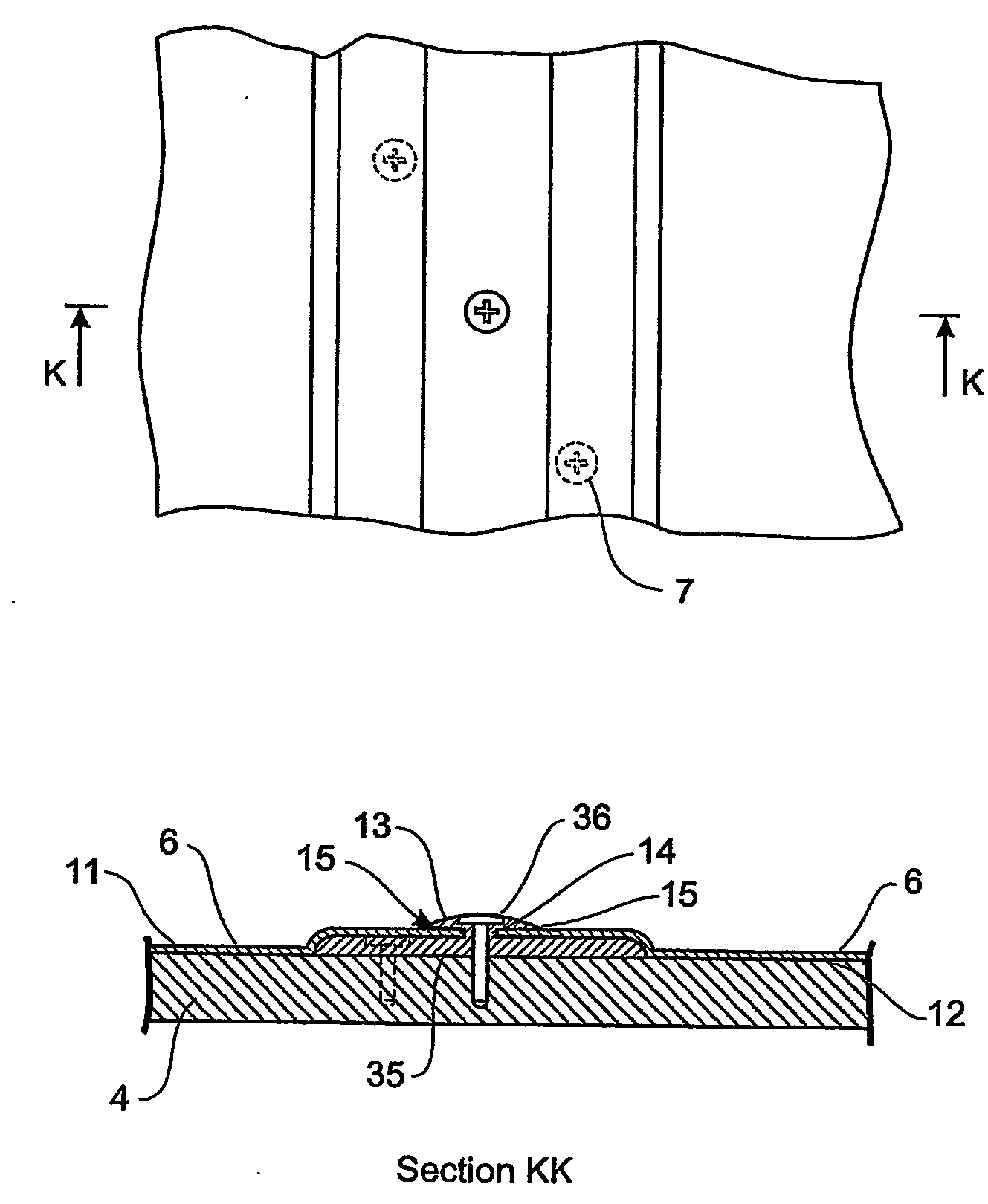
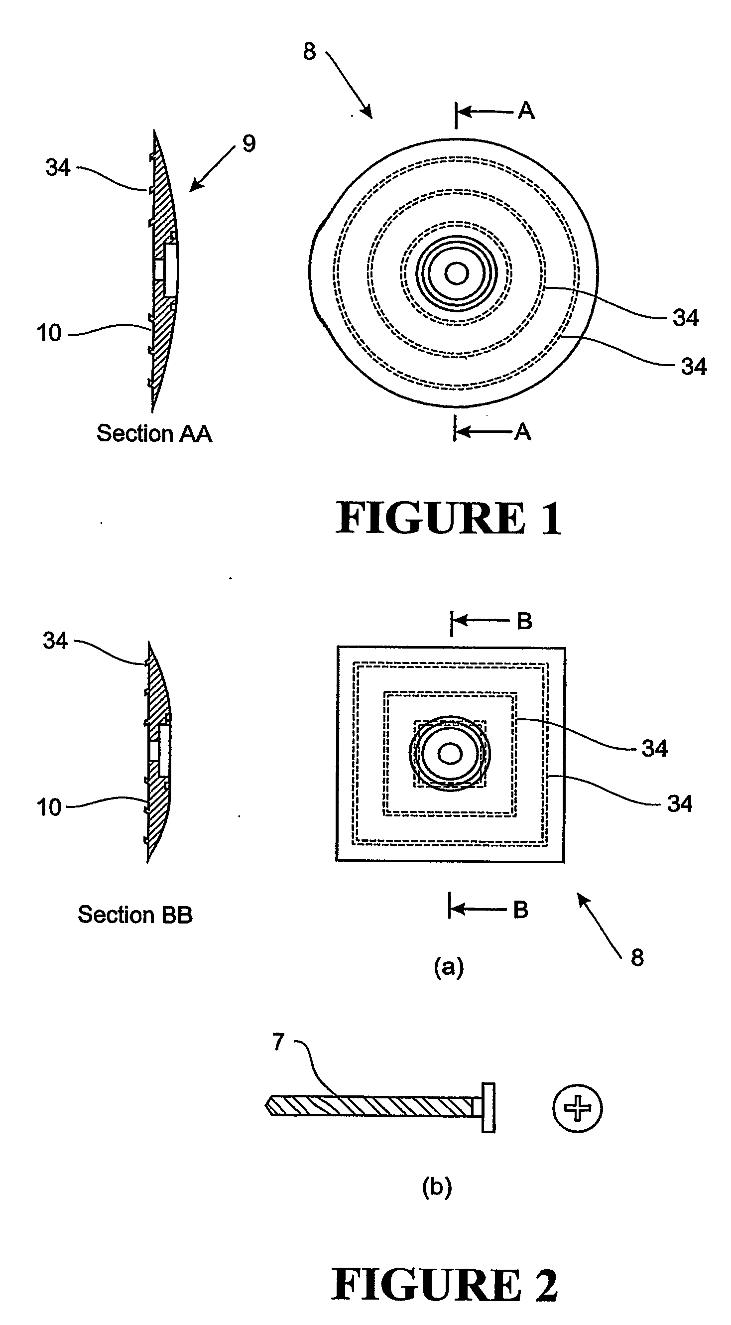
A building cladding has a cladding material (6) which is fusible and which attached to fastening (7) by fusing. The fastening penetrating the building substrate (4). By fusion to itself the cladding material forms a generally continuous membrane over the substrate. Preferably polyurethane is used as the cladding material fusible surface.

Description

FIELD OF THE INVENTION [0001] The field of the present invention relates to claddings systems for buildings or structures, particularly a cladding system relating to sealing a building or structure optionally with an in place continuous weatherproof membrane. BACKGROUND OF TH INVENTION [0002] For the weather proofing of a building, in particular the roof (but also applicable to side wall on other surface cladding), there are many systems available. [0003] For roofs these extend to tiles and other discreet forms of layered roofing protection such as long run steel and corrugated roofing. For walls there are similar type cladding systems of discreet tiles or sections to cover and seal the wall. Another class of cladding systems both for roofs and walls is to utilise a semi-continuous membrane which is laid, coated or otherwise applied to the surface to be sealed and which may be in-place sealed to form a continuous membrane, e.g. sheets which are laid down and then sealed to each othe...

Claims


Application Information

Patent Timeline
IPC IPC(8): E04B5/00E04B2/00E04D3/40E04D5/14E04D13/14
CPCE04D3/405E04D5/142E04D5/145E04D5/146E04D5/149E04D13/1407E04D13/1415
Inventor HAYNES, ANDREW LEONICHOLLS, CHRISTOPHER JOHNGIRDIU, GABRIEL IOANBUCKINGHAM, SAMUEL GWYNN
Owner HAYNES ANDREW LEO
Why Eureka
Try Eureka