Dynamic conversion circuit for a voltage regulator module

Active Publication Date: 2007-05-03
INFINEON TECH AMERICAS
View PDF34 Cites 33 Cited by
  • Summary
  • Abstract
  • Description
  • Claims
  • Application Information

AI Technical Summary

Benefits of technology

[0024] Activating the switch in accordance with the load transient may comprise activating the switch in accordance with at least one of: (i) a decrease in the output voltage of the DC-DC converter below a minimum output voltage; and (ii) an increase in output current of the DC-DC converter above an operating output current.
[0025] In one embodiment, activating the switch may comprise turning the switch on and off with a pulse train of constant duty cycle, the pulse train having a f

Problems solved by technology

However, the voltage drop of VRMs based on existing designs may be so large that the output voltage regulation limit may easily be exceeded.
However, such designs are not well-suited to the harsher dynamic requirements of next generation microprocessors.
Such filter capacitors are bulky and expensive.
However, the inductance can not be reduced unbounded, otherwise the output voltage ripple will increase above acceptable limits (e.g., above 10 mV for next generation microprocessors).
In addition, a larger ripple current through the filter inductor implies a larger RMS current through the power switches, which will reduce the overall efficiency of the VRM under steady state operation.
Moreover, even though the inductance can be reduced for a faster dynamic response, it is not enough to provide adequate response speed for future microprocessors if the output capacitance is required to be small to reduce cost and to satisfy size and volume constraints.
The more phases are in parallel, the smaller the ripple will be, but at the expense of increased circuit cost.
However, if the output current can be provided by a single phase VRM or a VRM with fewer phases, then adopting a multiphase topology or adding extra phases in parallel solely for the purpose of reducing the ripple voltage adds considerable complexity, size, and cost.
More importantly, it is very difficult for a conventionally-controlled multiphase VRM to achieve the dynamic response required by future microprocessors, without having very large output capacitance.
However, its dynamic performance is not superior to that of voltage mode control when a large transient occurs.
However, for an output current of 100 A or higher, it would be impractical to use a resistor to accurately and efficiently sense the current.
On the other hand, a current transformer is bulky and the sensed current must be averaged, resulting in fuirther increases in the reaction time and drop in the output voltage when a large load step happens.
However, this small room is far from being enough to handle the harsh dynamic requirements of the next generation microprocessors.
Moreover, the voltage droop control method also requires current sensing, which again is not very practical, as discussed above.
However, design of an efficient power converter operating at a very high frequency is difficult.
Further, the efficiency of a power converter decreases eventually to an unacceptable or unsatisfactory level as its operating frequency increases.
In general, increasing the switching frequency of a power converter solely for the purpose of improving the dynamic performance is not an optimum solution.
However, during normal steady state operation at full load, for example, the voltage drop across the linear regulator together with the DC current through it results in power loss.
However, loads such as the next generation CPU will demand a large load current, which would require a linear regulator to dissipate power excessively during normal steady state operation.
In addition, partitioning of the CPU into different power zones and an associated interface are required to make linear regulation feasible, because a single transistor is not capable of delivering a high current and at the same time effectively dissipating the heat due to the large power loss.
Wide acceptance of such designs is unlikely, especially when other solutions potentially exist.
Therefore, the linear regulator is impractical for applications in future microprocessors.
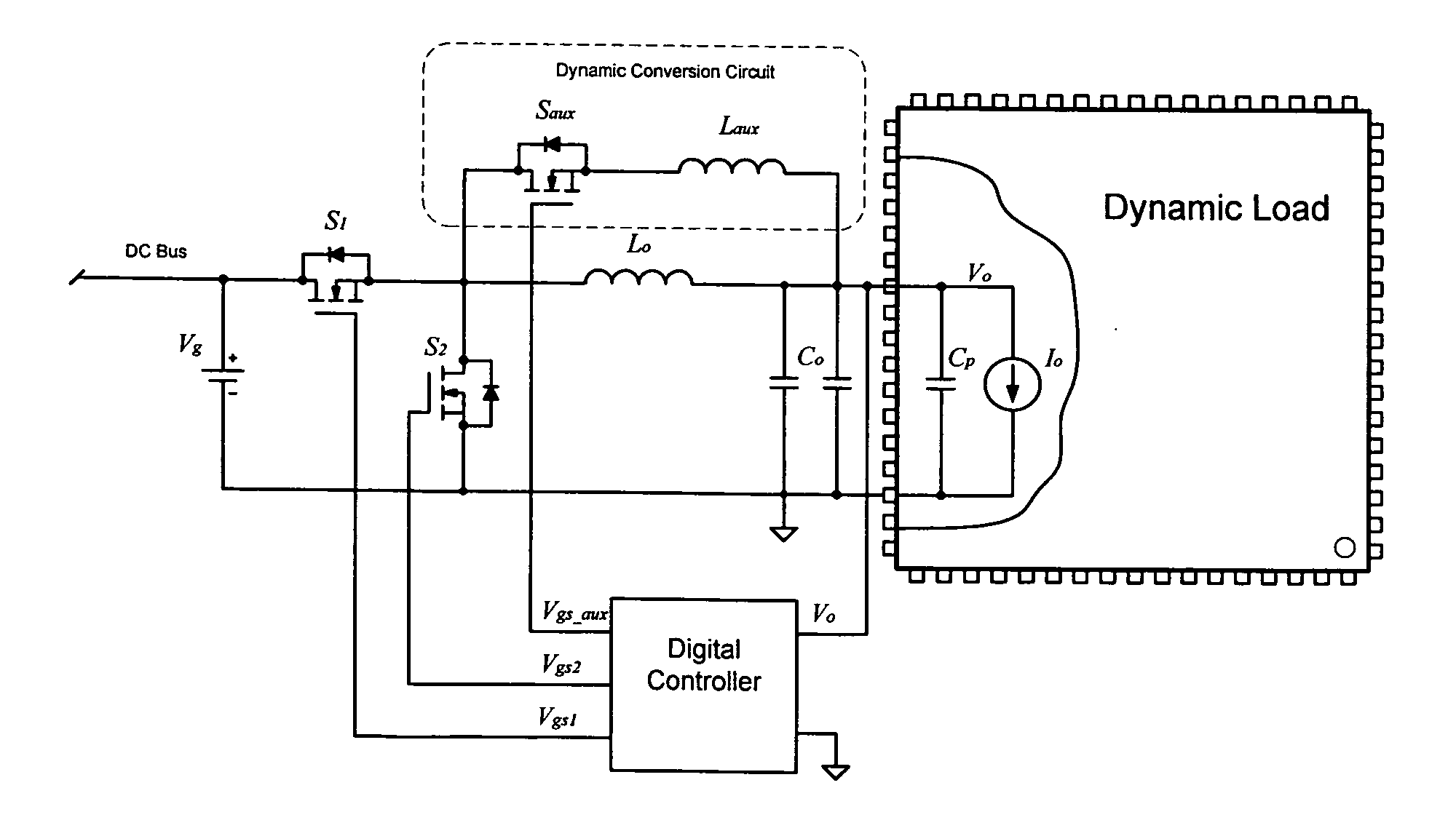
Relative to the basic buck converter, this design requires significantly more circuit components, which may be difficult and expensive to implement in a multiphase interleaved VRM, because all of the components need to be repeated for each phase.
Therefore, the voltage response during a load transient is not regulated and may exceed the specified limits of the output voltage during many load conditions.
However, the circuit and the control method are analog based, and, importantly, are not able to regulate the output voltage during the transient.

Method used


Image

  • Dynamic conversion circuit for a voltage regulator module
  • Dynamic conversion circuit for a voltage regulator module
  • Dynamic conversion circuit for a voltage regulator module

Examples


example

[0059] A voltage regulator module based on a buck converter, including a dynamic conversion circuit as described herein, suitably, was simulated in PSPICE v.9.0 and its performance evaluated with respect to a VRM based on a typical buck converter. The input and output voltages of the two VRMs was 12 Vdc and 1.5 Vdc respectively, and the switching frequency of the two circuits was 250 kHz. The rated output current was 25 A and the load transient was from 0.5 A to 25 A, at a slew rate of 1000 A / μs. The results of the simulation are shown in FIG. 9, where it can be seen that the voltage drop of the VRM of the invention was less than 10% of that of the typical VRM. According to the simulation, to avoid exceeding a 70 mV output voltage drop at a 100% load current transient (25 A), an output capacitance of only 500 μF was required. In contrast, the conventional voltage mode controlled single phase VRM needed at least 5000 μF output filter capacitance. This is an approximately 10-fold redu...


PUM


Abstract

The invention relates to a dynamic conversion circuit for improving the transient response of a switching DC-DC converter, such as in a voltage regulator module (VRM). The dynamic conversion circuit may be applied to a single phase or multiphase interleaved VRM of either isolated or non-isolated design configurations, and enhances power transfer from the input to the output of the DC-DC converter and tightly regulates the output voltage during harsh load current transients.

Description

FIELD OF THE INVENTION [0001] This invention relates generally to a voltage regulator module (VRM). In particular, the invention relates to a dynamic conversion circuit for enhancing the transient response of a DC-DC converter of a VRM for demanding loads such as microprocessors. BACKGROUND OF THE INVENTION [0002] A voltage regulator module (VRM) is used to regulate a DC voltage supplied to a load, such as microprocessor. A VRM includes a power converter, such as a DC-DC converter, and may include other components such as a controller for controlling operation of the power converter. An example of a DC-DC converter is a synchronous buck converter, as shown in FIG. 1, which has minimal components, and therefore is widely used in VRM applications. In microprocessor applications, the input voltage to the VRM is typically 12VDC. The output voltage may be 5.0VDC, 3.3VDC, or lower. [0003] As microprocessors become more advanced, required supply voltages become lower. Supply voltages are e...

Claims


Application Information

Patent Timeline
IPC IPC(8): G05F1/00
CPCH02M3/158
Inventor JAIN, PRAVEEN
Owner INFINEON TECH AMERICAS
Why Eureka
Try Eureka