Power source apparatus

Inactive Publication Date: 2005-10-13
TAIYO YUDEN KK
View PDF13 Cites 20 Cited by
  • Summary
  • Abstract
  • Description
  • Claims
  • Application Information

AI Technical Summary

Benefits of technology

[0009] One aspect of the invention reduces the number of switching elements required on the primary winding side of the output transformer and to decrease greatly the ripples contained in the output voltage.
[0010] Another aspect of the invention provides a novel power source apparatus which enables a soft start.

Problems solved by technology

Furthermore, in a low-voltage high-current environment, despite the fact that the effect of impedance components in the circuit becomes considerably large, presently available technology fails to produce parts with sufficiently low impedance.
For this reason, in order to inhibit the decrease in efficiency, increase in output voltage ripples, increase in switching surges, and the like caused by the impedance components, many power sources have to be implemented as multiphase configurations and an output smoothing capacitor has to be connected in parallel, resulting in a larger number of parts, increased cost, and enlarged size of the circuits.

Method used


Image

  • Power source apparatus
  • Power source apparatus
  • Power source apparatus

Examples


first preferred embodiment

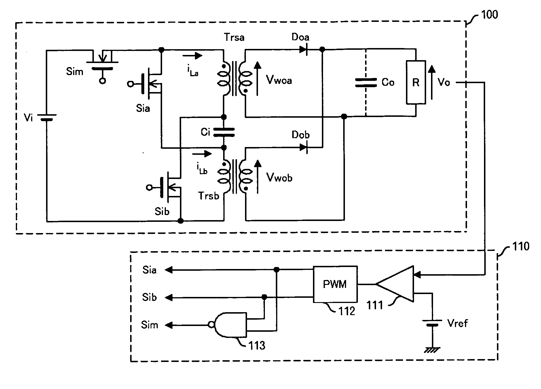
[0050] A circuit diagram of the first preferred embodiment of the present invention is shown in FIG. 1. A two-phase insulated converter 100 comprises an input DC power source Vi, switching elements Sim, Sia, Sib, which are a MOSFET (Metal-Oxide Semiconductor Field Effect Transistor), transformers Trsa and Trsb in which primary windings and secondary windings have inverted polarities, a capacitor Ci, diodes Doa and Dob which are rectifying elements, a smoothing capacitor Co, and a load R. In principle, the smoothing capacitor Co is not required, but it is shown herein because it is actually preferred to connect a capacitor with a capacitance lower than that of the conventional circuits. A control unit 110 comprises a reference voltage source Vref, a comparator 111, a PWM (Pulse Width Modulator) 112, and a NAND circuit 113.

[0051] The positive pole terminal of the input DC power source Vi is connected to the drain of the switching element Sim. The source of the switching element Sim i...

second preferred embodiment

[0075] A circuit diagram of the second preferred embodiment of the present invention is shown in FIG. 4. A control unit 110 has the same configuration in this embodiment, and the explanation thereof is herein omitted. The elements corresponding to the elements used in the first embodiment are assigned with the same reference symbols. A two-phase insulated converter 200 of the present embodiment comprises an input DC power source Vi, switching elements Sim, Sia, Sib, which are a MOSFET, transformers Trsa and Trsb in which primary windings and secondary windings have the same polarities, a capacitor Cia and a capacitor Cib, diodes Doa and Dob, which are rectifying elements, a smoothing capacitor Co, and a load R.

[0076] The positive pole terminal of the input DC power source Vi is connected to the drain of the switching element Sib and one terminal of the primary winding of the transformer Trsa. The other terminal of the primary winding of the transformer Trsa is connected to one term...

third preferred embodiment

[0093] A circuit diagram of the third preferred embodiment of the present invention is shown in FIG. 6. A control unit 110 has the same configuration in this embodiment, and the explanation thereof is herein omitted. Further, the elements corresponding to the elements used in the first embodiment are assigned with the same reference symbols. A two-phase insulated converter 300 of the present embodiment comprises an input DC power source Vi, switching elements Sim, Sia, Sib, Soa, Sob which are a MOSFET, transformers Trsa and Trsb in which primary windings and secondary windings have the inverted polarities, a capacitor Cia and a capacitor Cib, a smoothing capacitor Co, and a load R.

[0094] The positive pole terminal of the input DC power source Vi is connected to the drain of the switching element Sim. The source of the switching element Sim is connected to the drain of the switching element Sia and one terminal of the primary winding of the transformer Trsa. The other terminal of th...


PUM


Abstract

The number of switches on the primary winding side of a transformer is decreased and ripples contained in the output voltage are greatly reduced. In a state I, Sia and Sib are switched ON, in a state II, Sim and Sia are switched ON, in a state III, Sia and Sib are switched ON, and in a state IV, Sim and Sib are switched ON. As a result, in the states I to III, a transformer Trsa is connected to a capacitor Ci, in the state IV, the transformer Trsa is connected to an input power source Vi supplying an electric current in the direction opposite to that of the capacitor Ci. Further, in states I, III, and IV, the transformer Trsb is connected to the capacitor Ci, and in state II, the transformer Trsb is connected to the input power source Vi supplying an electric current in the direction opposite to that of the capacitor Ci. Further, in states I to III, the electric current generated on the secondary winding side of the transformer Trsa is supplied by a rectifying diode Doa to a load R, and in states I, III, and IV, the electric current generated on the secondary winding side of the transformer Trsb is supplied by a rectifying diode Dob to the load R.

Description

BACKGROUND OF THE INVENTION [0001] 1. Field of the Invention [0002] The present invention relates to a power source apparatus, more particularly, to a technology for reducing ripples contained in the output voltage. [0003] 2. Description of the Related Art [0004] Power sources for digital IC are required to supply a low-voltage high-current at a high throughput rate and to retain the fluctuations of an output voltage within a very narrow range. However, in general power source systems, a high-capacity smoothing capacitor is necessary at the output side to satisfy those requirements. Furthermore, in a low-voltage high-current environment, despite the fact that the effect of impedance components in the circuit becomes considerably large, presently available technology fails to produce parts with sufficiently low impedance. For this reason, in order to inhibit the decrease in efficiency, increase in output voltage ripples, increase in switching surges, and the like caused by the impeda...

Claims


Application Information

Patent Timeline
IPC IPC(8): H02J1/00H02M3/28H02M1/15H02M3/335
CPCH02M3/3353H02M1/15
Inventor HARADA, KOSUKENISHIJIMA, KIMIHIRO
Owner TAIYO YUDEN KK
Why Eureka
Try Eureka