Manufacturing method of producing ceramic honeycomb structure body
a technology of ceramic honeycomb and manufacturing method, which is applied in the field of manufacturing method of can solve the problems of decreasing the dimensional accuracy of the ceramic honeycomb structure body, deformation or cracking of the ceramic honeycomb structure body, and difficulty in the extrusion molding step of the conventional manufacturing method, so as to increase the dimensional accuracy of the ceramic honeycomb structure and high accuracy
- Summary
- Abstract
- Description
- Claims
- Application Information
AI Technical Summary
Benefits of technology
Problems solved by technology
Method used
Image

Examples
first embodiment
[0056] A description will be given of the manufacturing method of producing a ceramic honeycomb structure body according to the first embodiment of the present invention with reference to FIG. 1 to FIG. 5.
[0057] As shown in FIG. 1 to FIG. 5, the manufacturing method according to the first embodiment has the steps of an extrusion molding, a cutting, a drying, a working, and a burning.
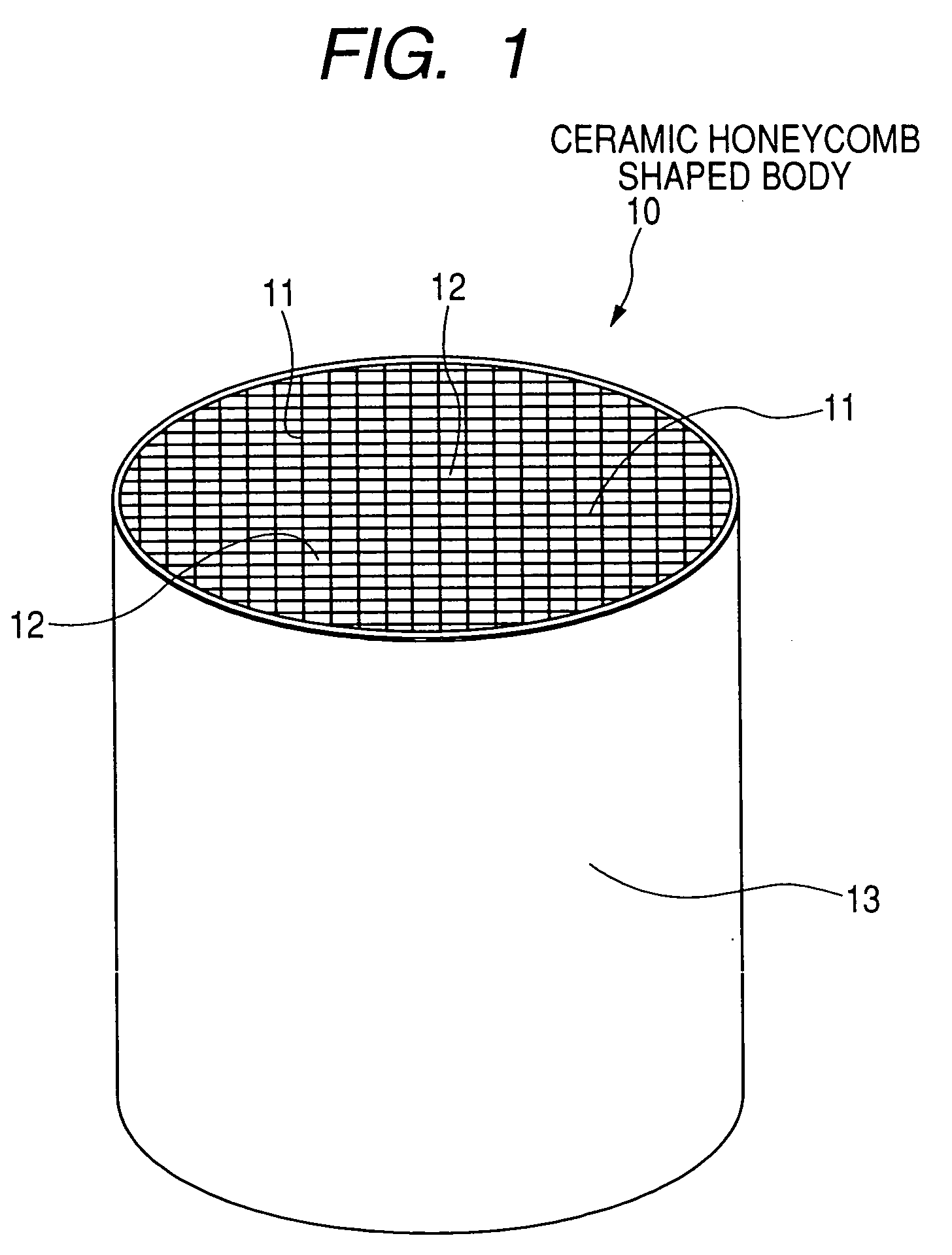
[0058] In the extrusion molding step, a ceramic raw material is extruded to produce a ceramic honeycomb molded body. The ceramic honeycomb molded body has an outer peripheral skin part 13, a plurality of cell walls 11 formed, in a honeycomb structure shape, in the inside area of the outer peripheral skin part 13, and a plurality of cells 12 surrounded by the plural cell walls 11. Each of the cells is a penetrate hole formed along a longitudinal direction or an axis direction of the ceramic honeycomb molded body.
[0059] In the cutting step, the ceramic honeycomb molded body is cut into a plurality of ce...
second embodiment
[0120] A description will be given of the manufacturing method of producing a ceramic honeycomb structure body according to the second embodiment of the present invention with reference to FIG. 8.
[0121]FIG. 8 is a perspective view showing a part of a structure of a cutting tool 3 to be used in the working step according to the second embodiment of the present invention;
[0122] As shown in FIG. 8, the cutting tool 3 to be used in the working step of the second embodiment has a curve shaped cutting tooth 31 formed at a front part 311 of the cutting tool 3. The front part 311 of the cutting tooth 31 has an acute angled shape.
[0123] Next, the manufacturing method of the second embodiment using the cutting tool 3 will be explained.
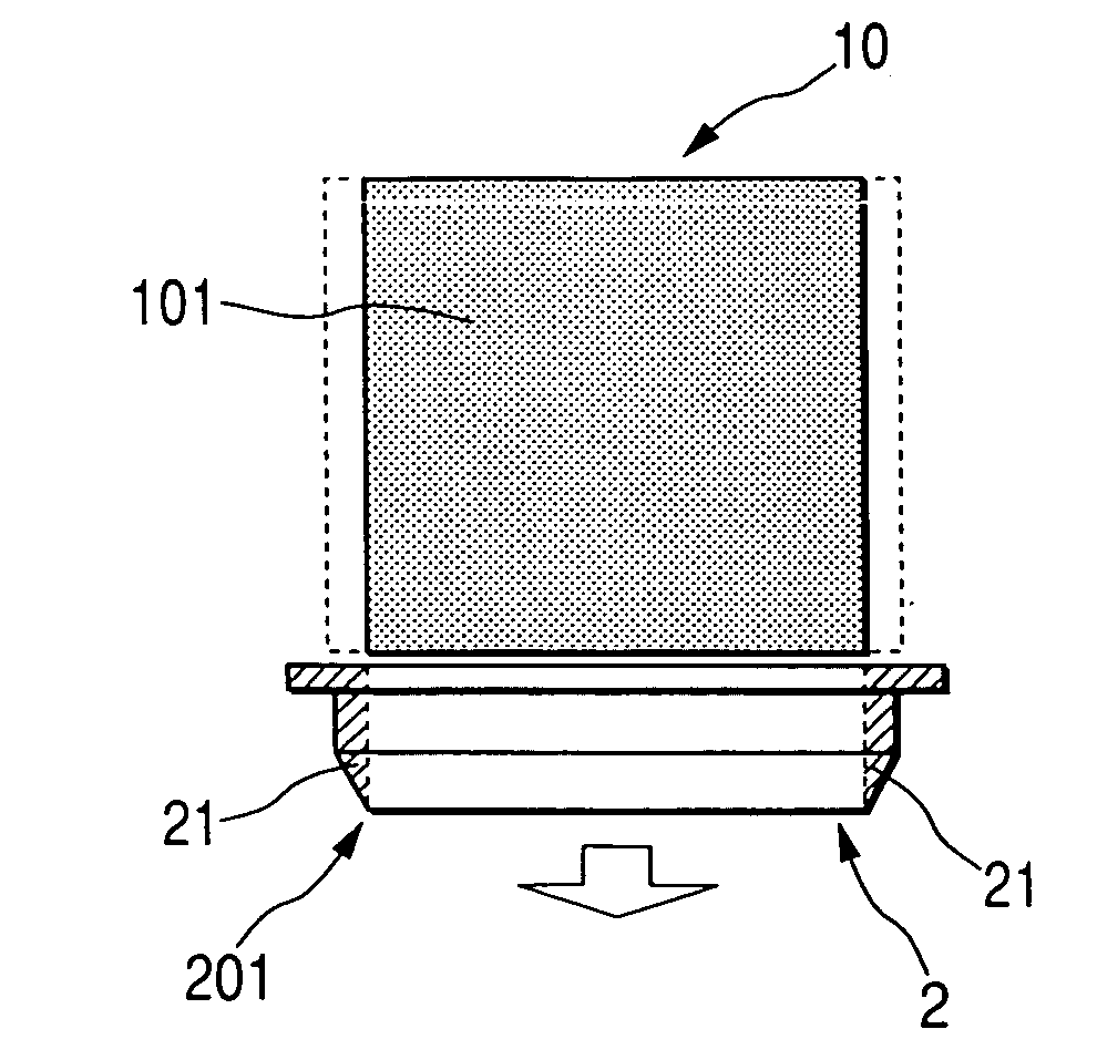
[0124] In the working step to perform a blanking process (namely, cutting and removing), the cutting tool 3 is moved in the axis direction from the upper position of the ceramic honeycomb shaped body 10 toward its bottom position while contacting the cutting...
third embodiment
[0136] A description will be given of the manufacturing method of producing a ceramic honeycomb structure body according to the third embodiment of the present invention with reference to FIG. 9 and FIG. 10.
[0137]FIG. 9 is a perspective view showing a structure of a rotary cutting tool 4 to be used in the working step in the manufacturing method according to the third embodiment of the present invention.
[0138]FIG. 10 is a schematic view showing cutting a ceramic honeycomb shaped body 10 in the working step by using the rotary cutting tool 4 shown in FIG. 9.
[0139] The manufacturing method of the third embodiment uses the rotary cutting tool 4 shown in FIG. 9. The rotary cutting tool 4 has a base body 40 and plural cutting tooth 411 formed on the outer peripheral surface of the base body 40.
[0140] A description will now be given of the manufacturing method, which uses the rotary cutting tool 4, of producing the ceramic honeycomb structure body 10 according to the third embodiment ...
PUM
| Property | Measurement | Unit |
|---|---|---|
| clearance angle | aaaaa | aaaaa |
| clearance angle | aaaaa | aaaaa |
| included angle | aaaaa | aaaaa |
Abstract
Description
Claims
Application Information
 - R&D
- Intellectual Property
- Life Sciences
- Materials
- Tech Scout
- Unparalleled Data Quality
- Higher Quality Content
- 60% Fewer Hallucinations
Browse by: Latest US Patents, China's latest patents, Technical Efficacy Thesaurus, Application Domain, Technology Topic, Popular Technical Reports.
© 2025 PatSnap. All rights reserved.Legal|Privacy policy|Modern Slavery Act Transparency Statement|Sitemap|About US| Contact US: help@patsnap.com