Eureka AIR delivers breakthrough ideas for toughest innovation challenges, trusted by R&D personnel around the world.

Photovoltaic roof-top components, a photovoltaic IRMA roofing system, and a photovoltaic roofing system

Inactive Publication Date: 2007-05-03
MERGOLA THOMAS J +1
View PDF14 Cites 42 Cited by
  • Summary
  • Abstract
  • Description
  • Claims
  • Application Information

AI Technical Summary

Benefits of technology

[0018] By replacing a traditional layer of ballast material in an IRMA roofing system with the photovoltaic panel and concrete topping on the insulation layer, the photovoltaic IRMA roofing system efficiently satisfies the predetermined minimum weight per unit area requirement of any specific roofing system while minimizing any risk of exceeding a maximum weight load of the roof. This is particularly valuable when improving an existing IRMA roof by removing existing ballast materials and replacing them with the combined weight of the concrete layer and the photovoltaic panels. This also adds insulation to enhance the energy efficiency of the building. The photovoltaic IRMA roofing system also minimizes a weight load, cost of materials and assembly for any new roof that is to include photovoltaic panels.
[0020] An alternative embodiment of the photovoltaic roofing system of the present invention is referred to for convenience as a “dew-point sensitive roofing system”, and includes the above described roofing membrane, insulation layer and photovoltaic panel above the insulation layer, and also includes a sub-membrane insulation layer secured between the top surface of the roof deck and the roofing membrane such as would occur in an installation of photovoltaic panels over an existing roof or as part of an engineered combination of photovoltaic panels and a new roofing system having a membrane above insulation and decking. The sub-membrane insulation layer defines a predetermined sub-membrane insulation layer thickness between the top surface of the roof deck and the roofing membrane. The above membrane insulation layer in this dew-point sensitive roofing system must define a predetermined thickness that is a function of the sub-membrane insulation layer thickness so that the above membrane insulation layer has a greater “R” (resistance to movement of heat) value than the sub-membrane insulation layer. This dew-point sensitive roofing system alternative embodiment of the invention provides advantages of a protected membrane (“inverted roofing membrane assemblies”, or by the acronym “IRMA”, or “PMR”) roofing system in all applications by combining the dew point sensitive system insulation with a ballast layer consisting of the weight of the photovoltaic glass panel and the weight of a cementitious face of an uppermost layer of insulation. The advantages include longer membrane life due to a more constant membrane temperature and preventing damaging ultraviolet rays from reaching the membrane.
[0024] Preferred embodiments of the improved photovoltaic roofing components and photovoltaic roofing system and improved photovoltaic insulation layer also include drainage channels that are both parallel to an axis of gravity flow of water draining through the system, and that are also not parallel to the axis of gravity of flow and that intersect with the channels parallel to the gravity axis of flow. This may appear as the insulation layer having an approximately checked appearance on a surface closest to the roofing membrane including gravity flow drainage channels and channels perpendicular to and intersecting with the gravity flow channels. Such various drainage channels enhance lateral movement of water to thereby provide for even more rapid movement of water through the system, so that, for example, snow-melt water, or water backed up above a temporary snow damn may readily move through the photovoltaic roofing system.
[0027] Any quick-disconnect photovoltaic panels may therefore be readily removed from a photovoltaic roofing system without disrupting the insulation layer below the photovoltaic panels, and without risk of damage to adjacent photovoltaic panels, to repair or to replace the removed panel, etc. Additionally, all of the quick-disconnect panels may be removed to be replaced with upgraded photovoltaic panels without disrupting the insulation layer thereby minimizing any risk of damage to the roof membrane, and further minimizing cost of such repairs or upgrades.
[0031] It is a more specific purpose to provide improved photovoltaic roofing components and a photovoltaic roofing system that may be customized for particular conditions of a specific roof deck to thereby enhance performance, service and longevity of the photovoltaic roofing system.

Problems solved by technology

However, the ballast materials add a substantial weight load to the roof, and also require substantial cost and effort in applying the ballast materials to the roof.
Consequently, such newly constructed buildings must design for the additional loads and existing IRMA roofs may present weight limitation challenges if it is desired to add a photovoltaic roofing system to the IRMA roof.
Other problems associated with roof-top assemblies using photovoltaic roofing components include efforts to minimize penetration and related possible leakage through the roofing membrane by apparatus used to secure the panels to the roof membrane; resistance to wind forces that may rip photovoltaic panels off of a roof deck; stabilizing temperatures experienced during operation of the photovoltaic panels; drainage of rain and melt water under such photovoltaic components; and a number of related challenges.
However, no known patent or known photovoltaic roofing system efficiently resolves major challenges that have become more pressing with the development of modern, stringent building codes.
By requiring such significant drainage slope, known photovoltaic modules are essentially incapable of effectively dealing with a substantial flow of water from upstream of the module in all types of flat or moderately sloped roof conditions.
In some circumstances, a sudden, high rain-fall rate may lead to such a flow of water from areas upstream of the modules and then onto the modules, so that the modules may be damaged dislodged from their positions on the roof and also causing damage to the membrane.
Additionally, it has been determined that standardized insulation layers beneath photovoltaic modules may give rise to unacceptable dew points below roofing membranes in certain roofing structures, thereby leading to unacceptable condensation of moisture below a roofing membrane upon a roofing deck.
Such condensation may lead to corrosion of metal roofing decks and / or rotting of wooden deck materials & membrane.
Other problems associated with such roofing systems using photovoltaic roof-top components include excessive weight of such known systems, and difficulties associated with repair or upgrading of the photovoltaic panel components of the roofing assemblies.
Some older flat roofs are only capable of supporting between four to five pounds per square foot, and most known photovoltaic roofing systems weigh substantially more.
While that may facilitate manufacture and installation, it is know that frequently only one photovoltaic panel may fail or be damaged by accidental impact by debris resulting from severe weather, falling installation tools, and / or misuse etc.
To remove and replace one or only several photovoltaic panels of such a system is extremely difficult where the photovoltaic panels are integral with spacers and / or an insulation layers below the panels.
Removal and disruption of a section of the insulation layer raises risks of damage to the underlying roofing membrane, and adjacent panels.
However, to upgrade known photovoltaic roofing systems may require removal of the entire system because the photovoltaic panels are known to be integral with insulation layers and spacers below the panels.

Method used


Image

  • Photovoltaic roof-top components, a photovoltaic IRMA roofing system, and a photovoltaic roofing system
  • Photovoltaic roof-top components, a photovoltaic IRMA roofing system, and a photovoltaic roofing system
  • Photovoltaic roof-top components, a photovoltaic IRMA roofing system, and a photovoltaic roofing system

Examples


Embodiment Construction

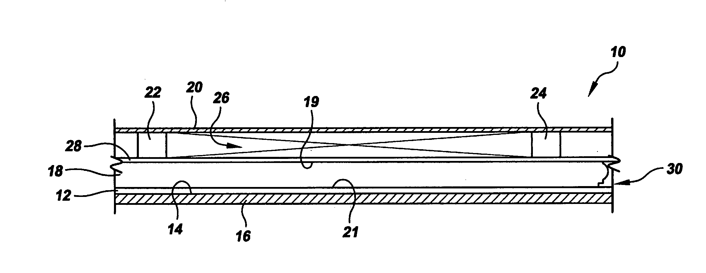
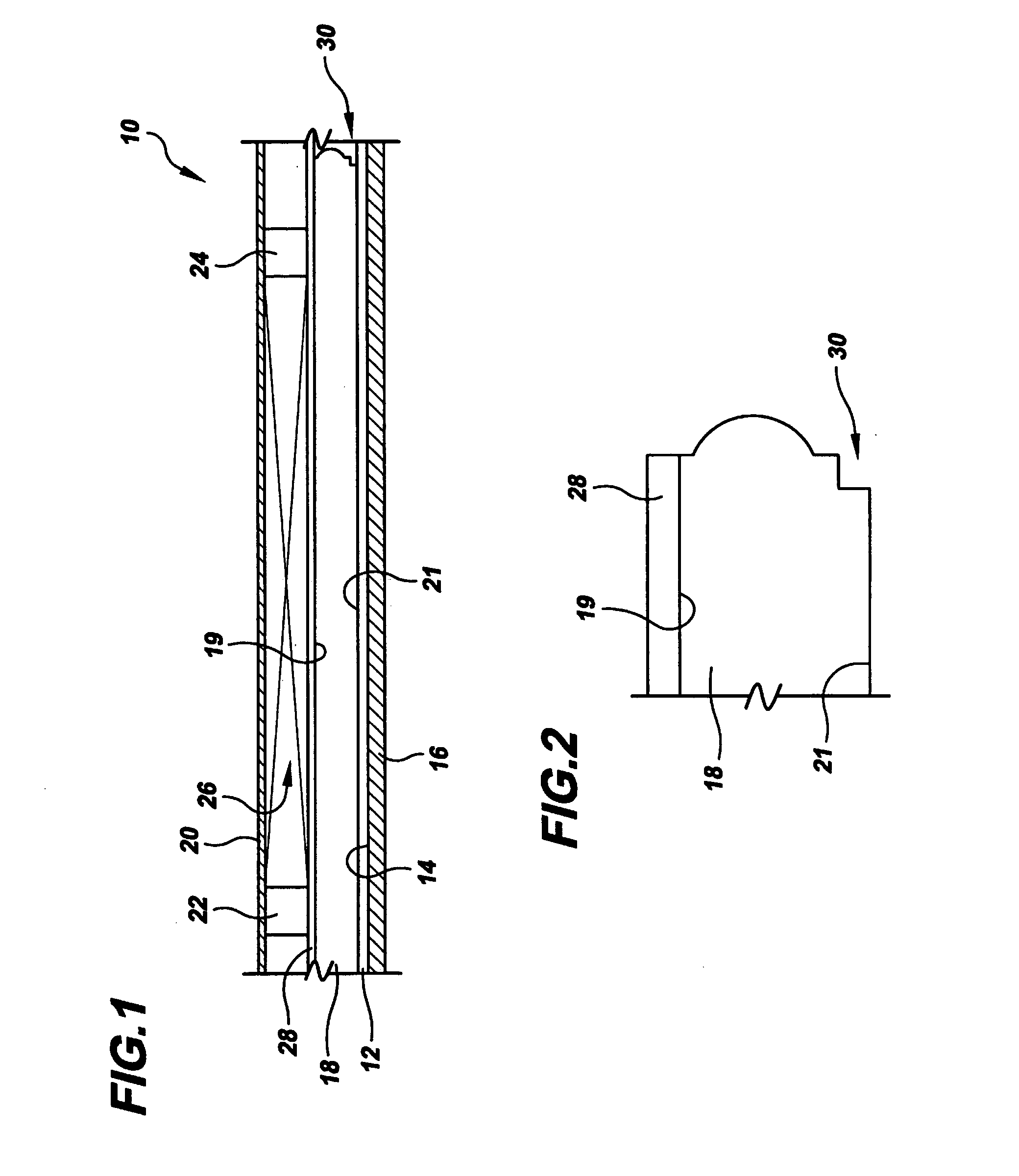
[0049] Referring to the drawings in detail, an improved photovoltaic roofing system is shown in FIG. 1, and is generally designated by the reference numeral 10. The system 10 includes a roofing membrane 12 overlying a top surface 14 of a roofing deck 16. An improved photovoltaic insulation layer 18 is above the roofing membrane 12. A photovoltaic panel 20 is above the insulation layer 18 and supported typically by way of insulation blocks or spacers 22, 24 that may provide an air space 26. (For purposes herein, the word “above” is to mean opposed to the direction of gravity. Additionally, hereinafter the phrase “secured to” is to mean either, “overlying”, “above” or “adjacent”, and does not mean that any securing apparatus or force is necessarily applied to adhere adjacent components to each other.) The improved insulation layer 18 may be secured to the photovoltaic panel 20 by being laminated to the panel 20, or to the panel spacers 22, 24, by lamination securing means known in the...


PUM


Abstract

An improved photovoltaic roofing system (10) includes a roofing membrane (12) overlying a top surface (14) of a roof deck (16), an insulation layer (18) above the roofing membrane (12) and a photovoltaic panel (20) above the insulation layer (18). The improved photovoltaic insulation layer (18) component defines a predetermined number of drainage channels (30) between the insulation layer (18) and the roofing membrane, and / or a predetermined insulation layer thickness, and the predetermined number of drainage channels (30) and / or thickness is a function of variable drainage requirements and / or variable insulation requirements of the roofing system (10). A photovoltaic IRMA roofing system (72) replaces traditional IRMA roofing system (73) ballast materials (79) with a combined weight of concrete topped (83) insulation layer and photovoltaic panels (80) to meet a predetermined minimum weight per unit area requirement of a specific roofing system (72).

Description

CROSS REFERENCE TO RELATED APPLICATION [0001] This Application claims the benefit of U.S. Provisional Patent Application Ser. No. 60 / 732,501 that was filed Nov. 2, 2005, entitled “Photovoltaic Roof-Top Components, Photovoltaic Roof-Top Assemblies, and Photovoltaic Roofing Systems”.TECHNICAL FIELD [0002] The present invention relates to photovoltaic roof-top components, photovoltaic roof-top assemblies, and photovoltaic systems that convert solar energy directly into electricity. [0003] BACKGROUND ART [0004] Roof-top assemblies that utilize solar energy are well known, and photovoltaic roof-top components that convert solar energy directly into electrical energy are increasingly common, especially on large commercial, essentially flat roofs. Such photovoltaic roof-top assemblies generally include photovoltaic panels on top of a roofing membrane that overlies a top surface of a roof deck. [0005] A well known roofing system includes use of a roofing membrane, and then a loosely laid in...

Claims


Application Information

Patent Timeline
IPC IPC(8): H02N6/00
CPCE04D13/0477E04D13/1662E04D13/1687F24J2/045F24J2/4614H02S20/23Y02B10/12Y02B10/20Y02E10/50F24J2002/5292Y02E10/40H01L31/052F24S20/67F24S40/44F24S2025/02Y02B10/10
Inventor MERGOLA, THOMAS J.ZEMSKY, MICHAEL
Owner MERGOLA THOMAS J
Why Eureka
Eureka Blog
Learn More