
Intraocular iontophoretic device and associated methods

a technology of ionophoretic device and ionophoretic gel, which is applied in the field of ophthalmology, can solve the problems of complex treatment of intermediate and posterior uveitis, systemic toxicities, and blindness of patients

Inactive Publication Date: 2007-04-26
ACIONT
View PDF27 Cites 18 Cited by
  • Summary
  • Abstract
  • Description
  • Claims
  • Application Information

AI Technical Summary

Benefits of technology

[0014] Additionally, the present invention provides methods for delivery of an active agent into the eye of a subject. For example, in one aspect a method is provided for controlling delivery of an active agent to a localized area in an eye of a subject. Such a method may include positioning a device according to aspects of the present invention on an eye surface where the device has an inter-electrode distance between the first electrode assembly and the second electrode assembly that controls the depth and extent of penetration of the active agent within the eye, and iontophoretically delivering the active agent in the eye with the first electrode assembly. The active agent delivered into the eye may provide immediate therapeutic effect, sustained therapeutic effect, or both immediate and sustained therapeutic effect.

Problems solved by technology

If left untreated, uveitis leads to blindness.
Treatments of intermediate and posterior uveitis are complicated by the inaccessibility of the posterior eye to topically applied medications.
Therefore large systemic doses are needed to treat intermediate and posterior uveitis, which often result in systemic toxicities including immunosuppression, adrenal suppression, ulcerogenesis, fluid and electrolyte imbalances, fat redistribution and psychological disorders.
Intravitreal injections are necessary because periocular injections and systemic administration do not deliver efficacious amounts of antibiotics to the target sites in the eye.
While intravitreal and periocular injections are preferable to systemic administration, the half-life of most injected compounds in the vitreous is relatively short, usually on the scale of just a few hours.
Therefore, intravitreal injections require frequent administration.
The repeated injections can cause pain, discomfort, intraocular pressure increases, intraocular bleeding, increased chances for infection, and the possibility of retinal detachment.
The major complication of periocular injections is accidental perforation of the globe, which causes pain, retinal detachment, ocular hypertension, and intraocular hemorrhage.
Therefore, these methods of ocular drug delivery into the posterior of the eye have significant limitations and major drawbacks.
In addition, injections are very poorly accepted by patients.
These methods also involve high healthcare cost due to the involvement of skilled and experienced physicians to perform the injections.
One potential problem with present ocular iontophoretic methods and devices concerns the actual delivery, or rather, the non-delivery of the drug into the eye tissue.
Such divergence of the electric current will decrease the efficiency of drug delivery to the target sites in the eye, and as a result, much of the drug may be delivered into the tissues surrounding the eye rather than into the eye per se.
Therefore, in many cases, traditional iontophoresis must be repeated as frequently as intravitreal injections, leading to patient inconvenience, increased costs, and increased possibility of untoward effects caused by the iontophoretic treatment itself.
The problem of patient compliance may be compounded by the need to receive daily treatment in a medical facility with high healthcare costs and limited resources and practitioners for treating retinal diseases.
Existing ocular iontophoresis systems are not patent-friendly, require multiple parts and assembly to practice, and include either clumsy or complicated procedures.
Paraprofessional and / or in-home self administration use of such devices are precluded by the technical complexity of many existing iontophoretic devices, as well as the costs of expensive dose-controlling equipment.
Individuals have a greater tendency to deviate from a medication regimen when required to leave home for medical treatment, particularly when such treatment is frequent.

Method used


Image

  • Intraocular iontophoretic device and associated methods
  • Intraocular iontophoretic device and associated methods
  • Intraocular iontophoretic device and associated methods

Examples


Embodiment Construction

[0023] Before the present systems and methods for ocular drug delivery are disclosed and described, it is to be understood that this invention is not limited to the particular process steps and materials disclosed herein, but is extended to equivalents thereof, as would be recognized by those ordinarily skilled in the relevant arts. It should also be understood that terminology employed herein is used for the purpose of describing particular embodiments only and is not intended to be limiting.

[0024] It must be noted that, as used in this specification and the appended claims, the singular forms “a,”“an,” and, “the” include plural referents unless the context clearly dictates otherwise. Thus, for example, reference to “a polymer” includes reference to one or more of such polymers, and “an excipient” includes reference to one or more of such excipients.

DEFINITIONS

[0025] In describing and claiming the present invention, the following terminology will be used in accordance with the d...


PUM


Abstract

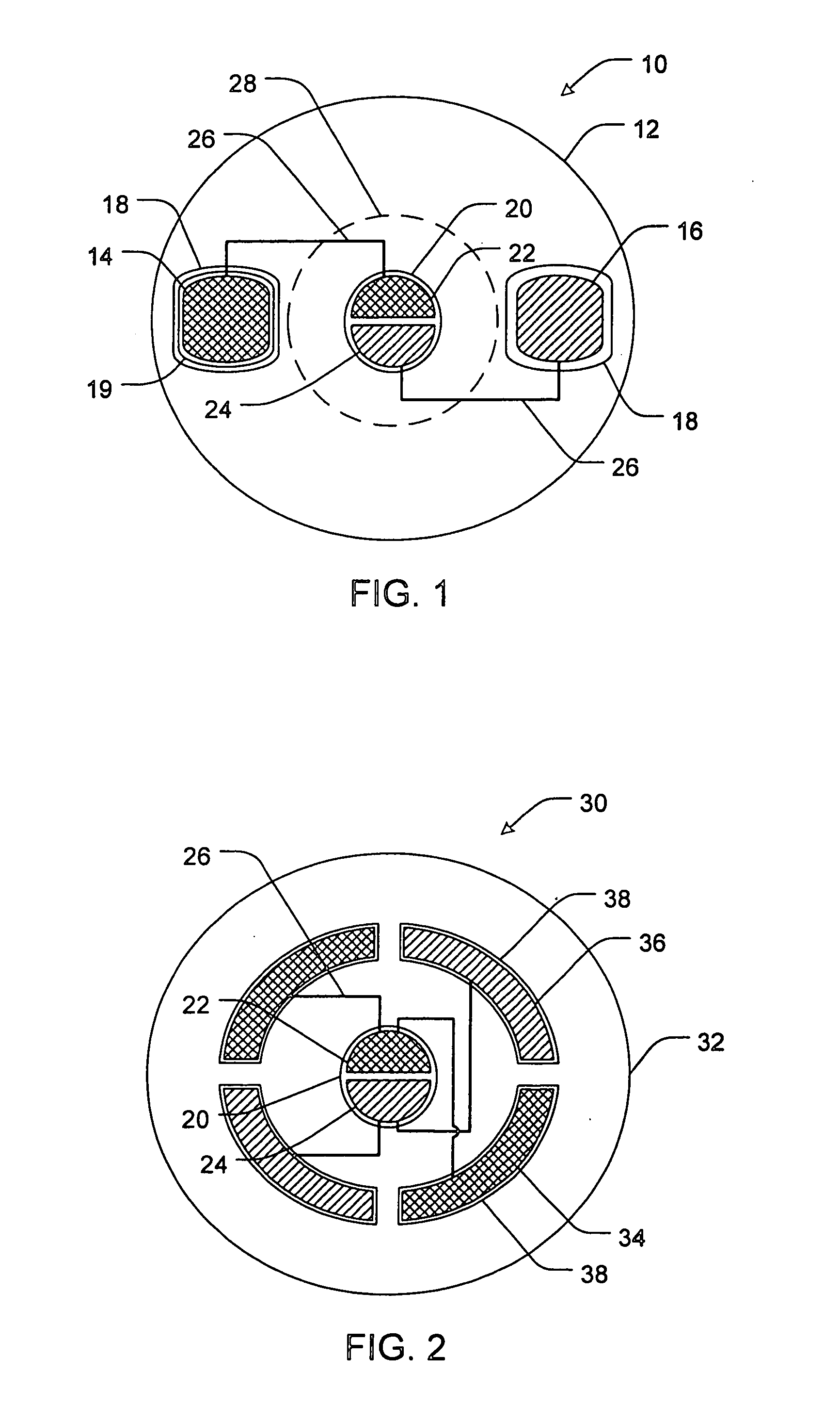
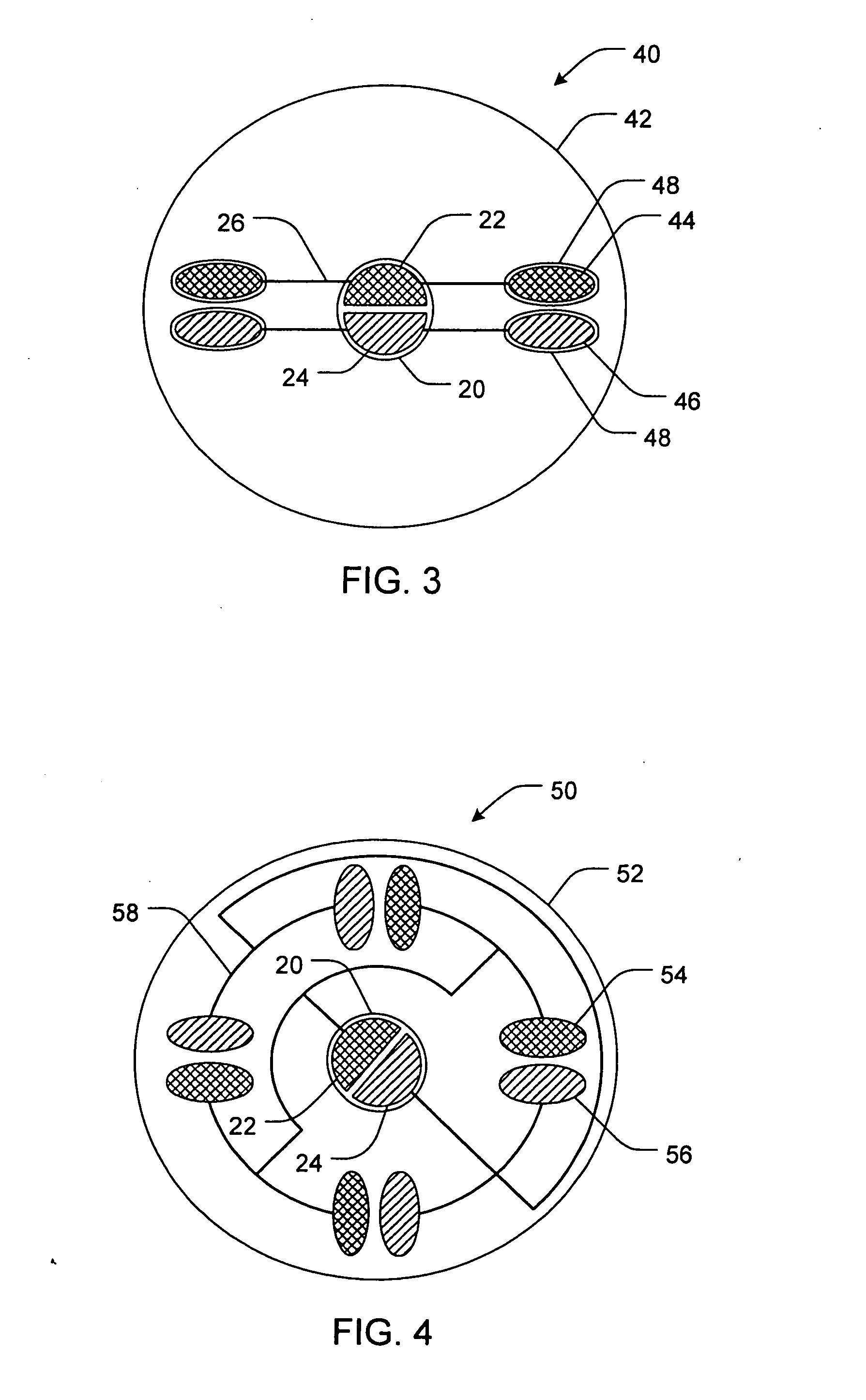
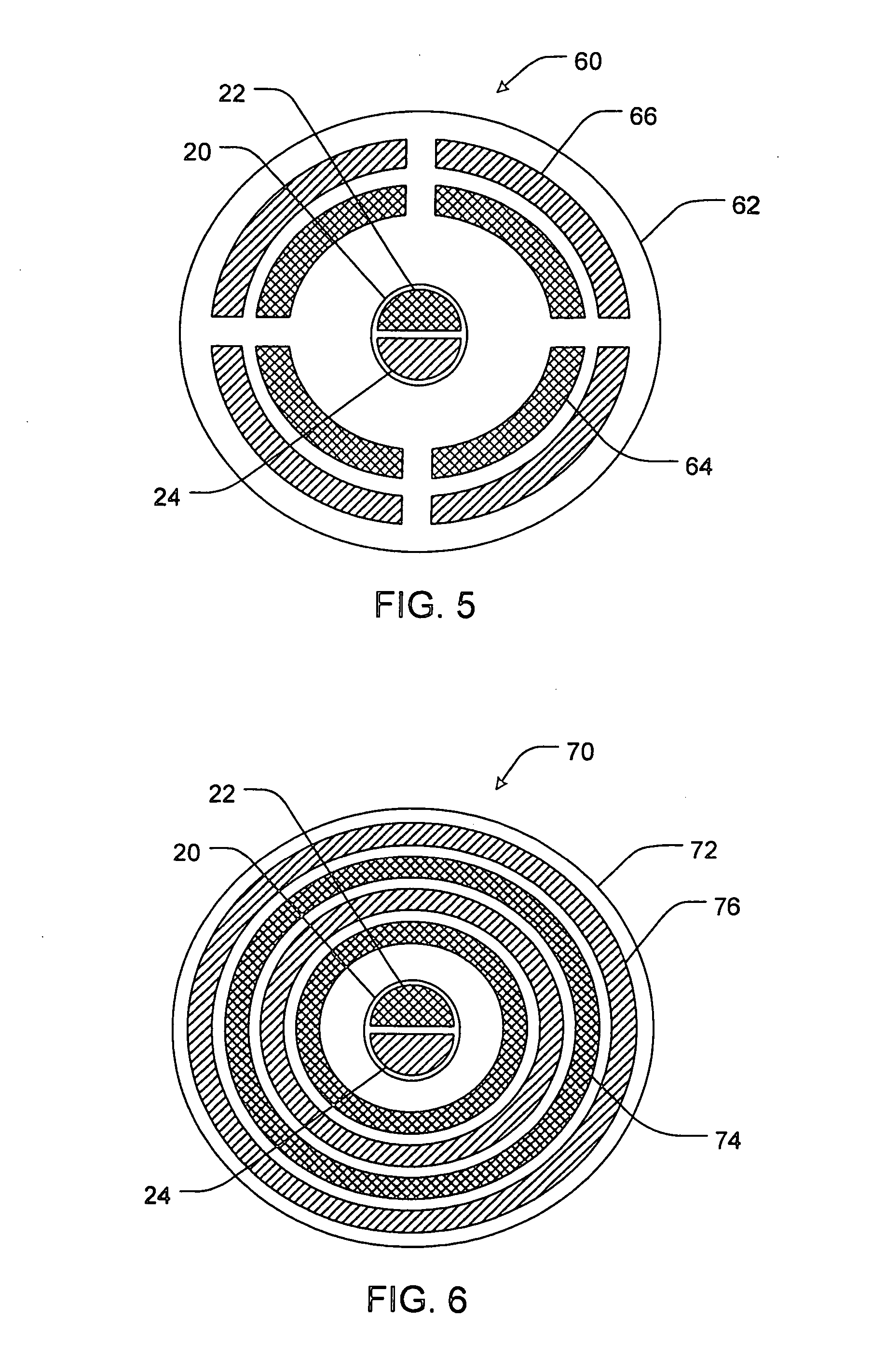
The present invention includes methods and devices for delivering an active agent into the eye of a subject. One such device may include an anode assembly having an anode housing and an anode configured to electrically couple to a power source, the anode assembly being configured to contact and remain against a surface of the eye. The device may also include a cathode assembly having a cathode housing and a cathode configured to electrically couple to the power source, the cathode assembly being configured to contact and remain against the surface of the eye. Additionally, the device may include at least one active agent reservoir functionally associated with at least one of the anode assembly and the cathode assembly.

Description

PRIORITY DATA [0001] This application claims the benefit of U.S. Provisional Patent Application Ser. No. 60 / 729,980, filed on Oct. 24, 2005, which is incorporated herein by reference. This application also claims the benefit of U.S. patent aqpplication Ser. Nos. 11 / 238,144 and 11 / 238,104, both filed on Sep. 27, 2005, both of which are incorporated herein by reference.FIELD OF THE INVENTION [0002] The present invention relates to systems, methods, and devices for the delivery of an active agent following minimally invasive or noninvasive delivery thereof through a localized region of a subject's body tissue, particularly the eye. Accordingly, the present invention involves the fields of chemistry, pharmaceutical sciences, and medicine, particularly ophthalmology. BACKGROUND OF THE INVENTION [0003] Posterior and intermediate eye diseases that require ocular drug delivery to prevent blindness include uveitis, bacterial and fungal endophthalmitis, age-related macular degeneration, viral...

Claims


Application Information

Patent Timeline
Patent Type & Authority Applications(United States)
IPC IPC(8): A61N1/30
CPCA61N1/044A61N1/0448A61N1/306
Inventor HIGUCHI, JOHN W.LI, S. KEVIN
Owner ACIONT
Learn More