
Image forming apparatus, and exposure control method therefor

an image forming apparatus and exposure control technology, applied in the field ofelectrophotographic image forming apparatus and an exposure method therefor, can solve the problems of image noise generated particularly in the case, and achieve the effect of preventing the generation of image noise and reducing the dispersion of dot reproducibility

Active Publication Date: 2007-04-19
KONICA MINOLTA BUSINESS TECH INC
View PDF7 Cites 0 Cited by
  • Summary
  • Abstract
  • Description
  • Claims
  • Application Information

AI Technical Summary

Benefits of technology

[0005] An object of the present invention is to provide an image forming apparatus and an exposure control method therefor, which can suppress generation of image noise by optimum exposure control.
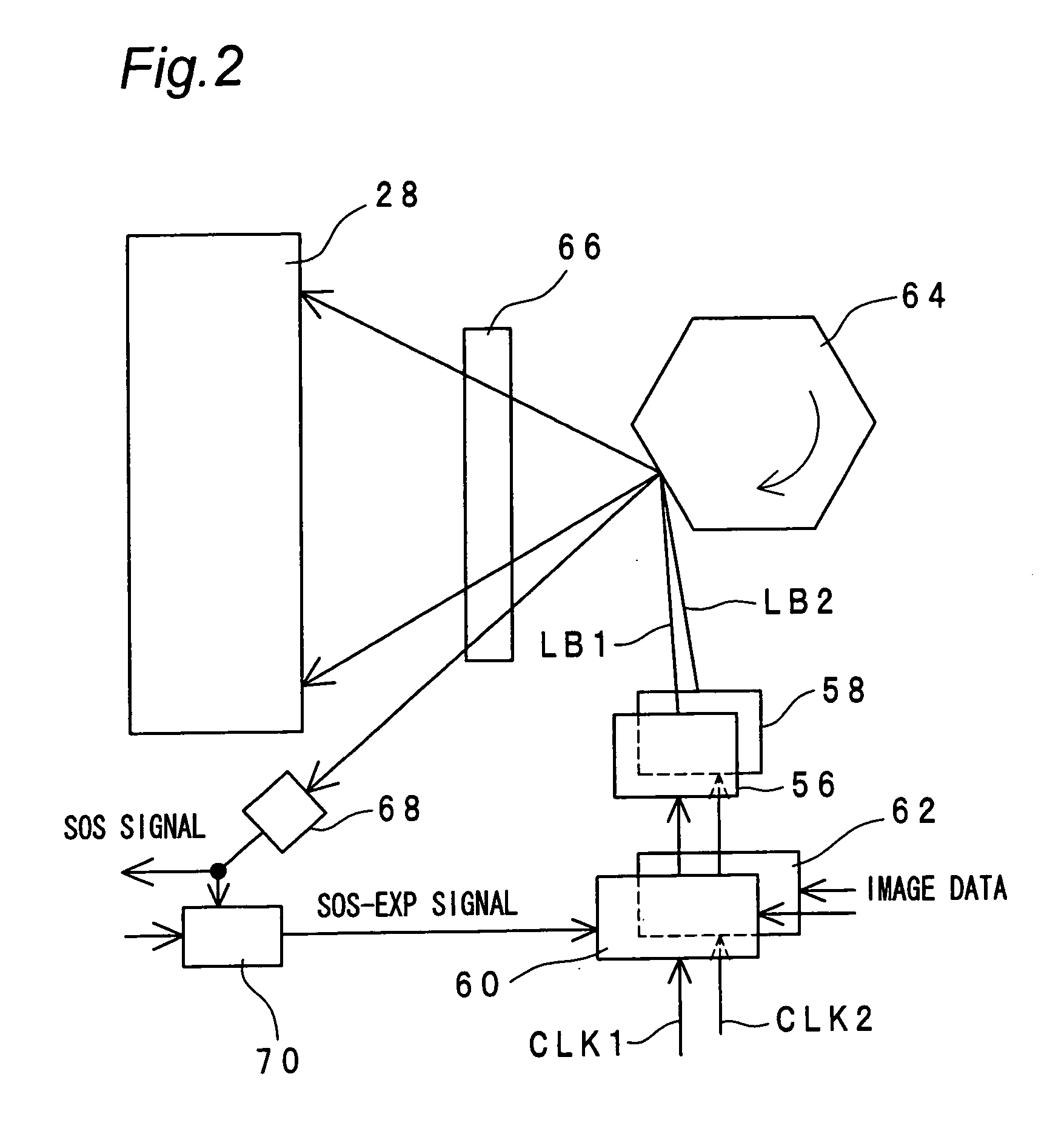
[0020] According to the image forming apparatus and the exposure control method therefor in the present invention, for example, detecting the toner density of each pattern formed by a plurality of exposure light sources and controlling the respective exposure light sources based on the detection result allows optimum control of the respective exposure light sources, which makes it possibly to eliminate dispersion of dot reproducibility on the photoreceptor in the respective exposure light sources and to prevent generation of image noise.
[0021] Moreover, by attaining the correlation between the first and the second exposure light sources based on the detection result by the sensor and storing the attained correlation, it becomes possible to form a specified pattern with use of only the first exposure light source, detect the pattern by the sensor, determine a control value for the first exposure light source based on the detection result by the sensor, and determine a control value for the second exposure light source based on the control value for the first exposure light source in conformity with the attained correlation, which eliminates the necessity of forming a toner pattern with use of the second exposure light source in the subsequent image stabilization control, thereby allowing reduction in time taken for control operation and reduction in toner consumption amount.

Problems solved by technology

In this type of image forming apparatuses, if dots formed on the photoreceptor by the respective exposure light sources have variations between the respective exposure light sources, then image noise is generated particularly in the case of forming halftone images.

Method used


Image

  • Image forming apparatus, and exposure control method therefor
  • Image forming apparatus, and exposure control method therefor
  • Image forming apparatus, and exposure control method therefor

Examples


Embodiment Construction

[0028]FIG. 1 is an overall structure view showing a tandem-type full-color copier 10 as an image forming apparatus in one embodiment of the present invention. The copier 10 is composed of an automatic document feed section 12, an image scanner section 14, and an image forming section 16.

[0029] The automatic document feed section 12 sequentially transports original documents loaded on its upper section one by one onto a platen glass 18 of the image scanner section 14, and transports the documents back one by one onto the upper section of the automatic document feed section 12 after document images are scanned.

[0030] The image scanner section 14 has a scanner optical system 20 and an image processing section 22. The scanner optical system 20 scans the image of a document transported onto the platen glass 18 while moving in an arrow A direction. The scanned document image data is inputted into the image processing section 22. If the inputted document image data is a color image, the ...


PUM


Abstract

An image forming apparatus of the invention includes an image carrier, an exposure device performing exposure for forming a toner image on a surface of the image carrier and having at least a first exposure light source and a second exposure light sources a sensor for detecting specified patterns, which are formed on the image carrier at a specified time with use of the first and second exposure light sources, a storing unit for storing a correlation, which is attained from a detection result by the sensor, between the first and second exposure light sources, and a controller for controlling the first and second exposure light sources based on the correlation.

Description

RELATED APPLICATION [0001] This application is based on Japanese Patent Application No. 2005-301639, the content of which is incorporated herein by reference. BACKGROUND OF THE INVENTION [0002] The present invention relates to an electrophotographic image forming apparatus and an exposure method therefor. [0003] Apparatuses conventionally known as electrophotographic image forming apparatuses include those executing image stabilization control composed of forming a plurality of specified toner patterns with varied intensities of laser emission from a laser diode (LD) serving as an exposure light source of an exposure device, detecting the density of each toner pattern by a sensor, attaining the relation between the laser emission intensity and the toner density based on attained detection results, and determining an optimum intensity of light emission which makes it possible to provide an optimum density based on the attained relation, and executing image formation with the determin...

Claims


Application Information

Patent Timeline
Patent Type & Authority Applications(United States)
IPC IPC(8): B41J2/385
CPCB41J2/473
Inventor SAKAI, TETSUYAHIRATA, KATSUYUKIISONO, TATSUYAHARASHIMA, TAKASHITSUBOI, TOSHIO
Owner KONICA MINOLTA BUSINESS TECH INC
Learn More