
Dynamic control of dilution ventilation in one-pass, critical environments

a technology of dilution ventilation and dynamic control, applied in ventilation systems, heating types, instruments, etc., can solve the problems of wasting resources, creating allergic reactions in individuals, and fresh outdoor air, and achieve the effect of low cos

Inactive Publication Date: 2007-04-12
DESROCHERS ERIC M +1
View PDF17 Cites 96 Cited by
  • Summary
  • Abstract
  • Description
  • Claims
  • Application Information

AI Technical Summary

Benefits of technology

This approach significantly reduces energy consumption by lowering airflow during clean conditions and ensures rapid contaminant removal during spills, enhancing safety and efficiency in critical environments.

Problems solved by technology

In particular, the exposure of these people to animal allergens, such as rat urine protein (RUP) or mice urine protein (MUP), that is often carried in the air on particulates can over time sensitize the animal care workers and researchers, and create allergic reactions in these individuals from the animals via contaminated air in the facility.
Accordingly, the minimum fixed air changes requirements for 100% outside air in conventional laboratory, vivarium, or other dilution ventilation systems often results in wasted resources (i.e., fresh outdoor air) and unnecessarily excessive operating costs as well as high up front capital costs for sufficient sizing of the building's heating, ventilating and air conditioning system also referred to as the HVAC system.
First, the numbers of laboratory fume hoods and related special exhaust devices has decreased.
Although in the early 90's the amount of lab instrumentation increased significantly, over time this equipment has become smaller and more energy efficient.
Although this approach can save energy it has several safety problems that negate its prudent use.
For example, a spill or release of hazardous vapors can occur during an unoccupied time increasing the level of contaminants in the air above safe levels.
If someone were to walk into the space during this scheduled unoccupied time, they could be injured by the higher level of contaminants in the air.
Furthermore, occupancy detectors can have problems with detecting people in a broken up space with many barriers such as lab shelves and equipment between the sensor and the occupants.
They also need to constantly see motion to operate and may fail to see someone quietly reading with insufficient motion to trigger the higher safe airflow.

Method used


Image

  • Dynamic control of dilution ventilation in one-pass, critical environments
  • Dynamic control of dilution ventilation in one-pass, critical environments
  • Dynamic control of dilution ventilation in one-pass, critical environments

Examples


Embodiment Construction

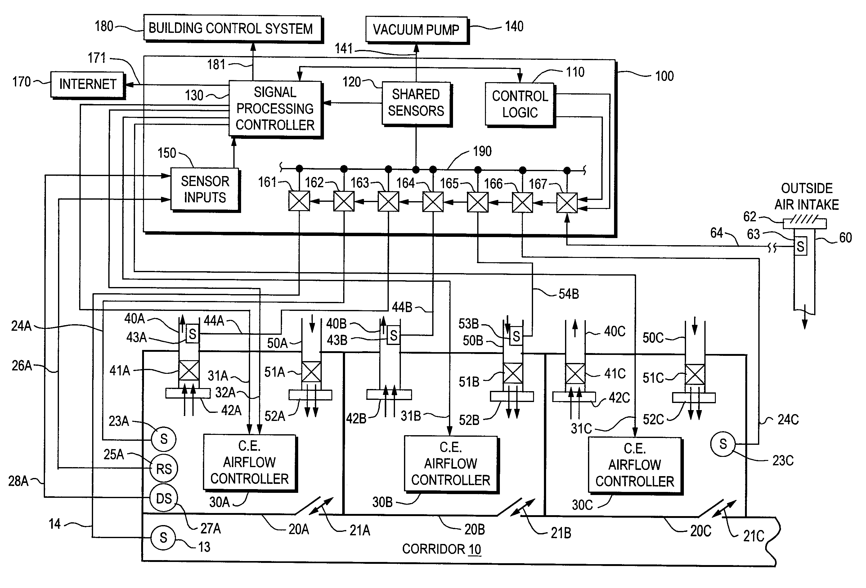
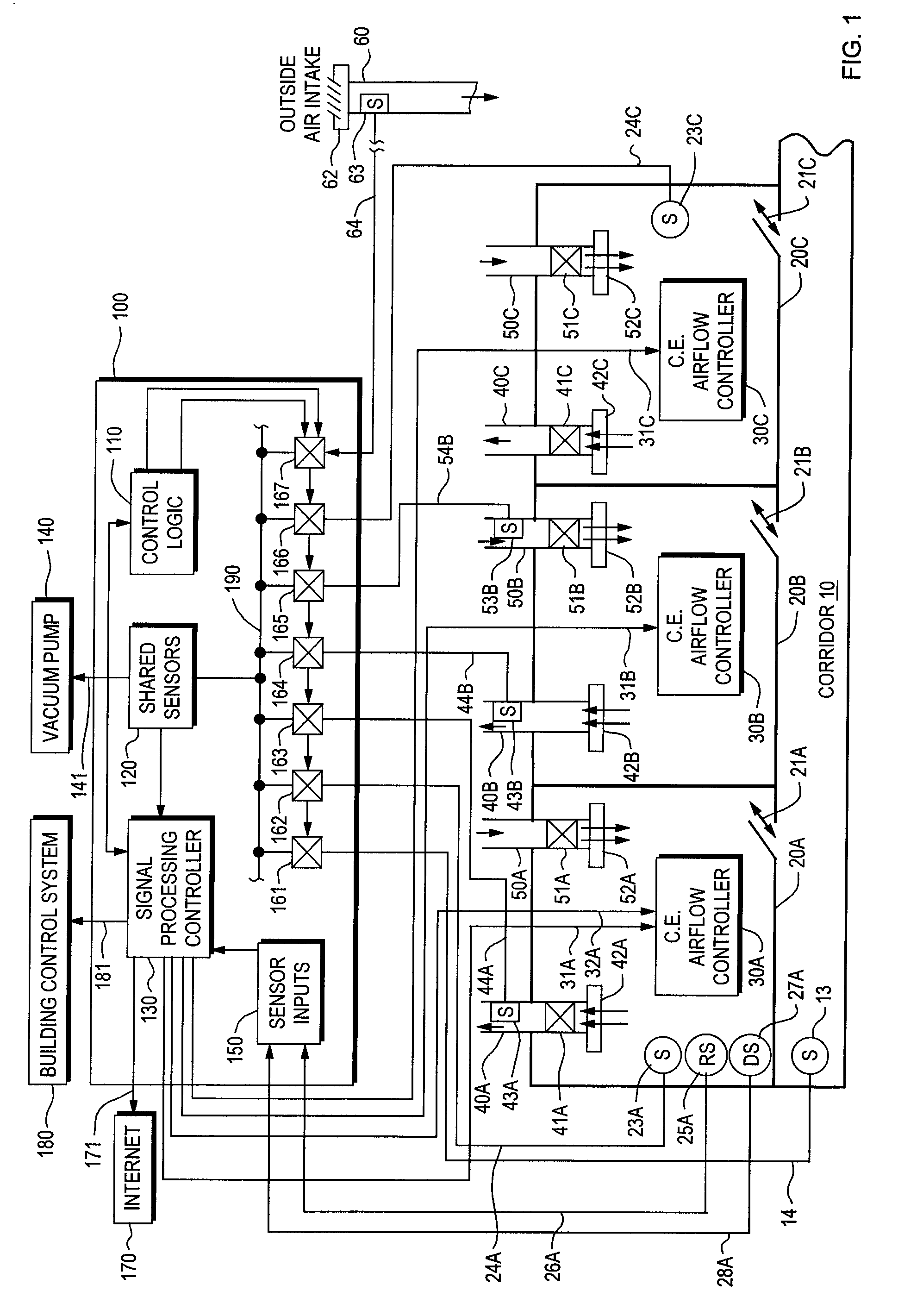
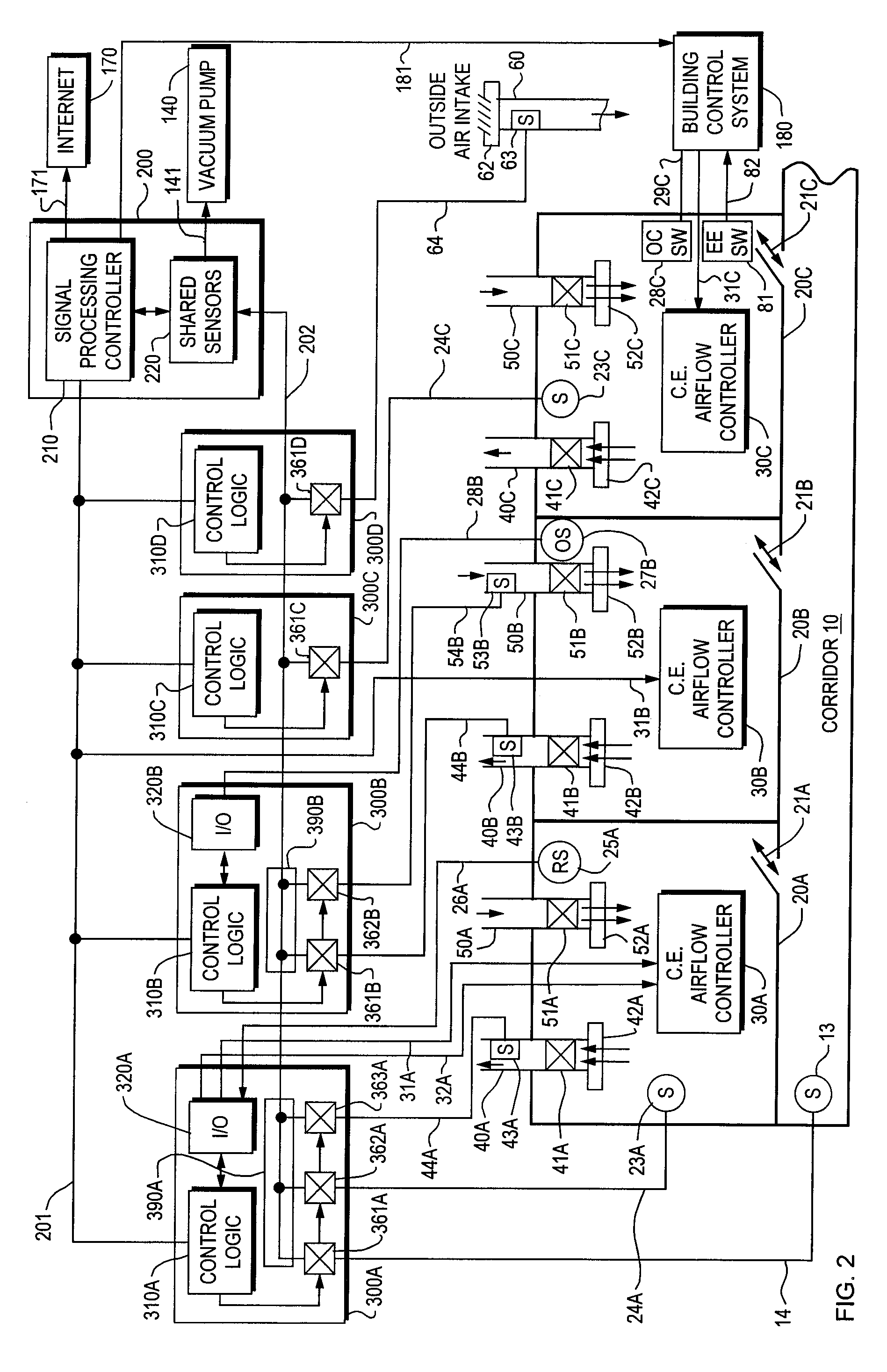
[0052]FIGS. 1, 2 and 6 all show a typical set of monitored critical environments or rooms 20A, 20B, and 20C that have doors entering a corridor 10 that is also being monitored. Due to a positive or negative pressurization of the critical environments, an offset may exist between the critical environment space or area and an adjacent space. An example of this is shown in FIGS. 1, 2 and 6 as offset airflow 21A, 21B, and 21C between the spaces 20A, B, and C and corridor 10. Although the diagrams show three rooms and a corridor, the present invention may be used with any plurality of rooms or spaces including corridors or other adjacent spaces that are also being monitored, such as for example, two or more critical environments, or one corridor plus one or more spaces. Note also that, although the critical environments shown in the Figures are enclosed within walls, critical environments in the context of this invention may also be a section or area of a room having no walls or partitio...


PUM


Abstract

A dilution ventilation control system for use in a one-pass, critical environments comprising: one or more one-pass, critical environments comprising, a variable source of supply airflow volume, an exhaust for completely exhausting the airflow volume supply from the critical environment and from a building comprising the critical environment through one or more exhaust ducts; and at least one an airflow control device provided in one or more of the ducts to vary the exhaust airflow volume from the critical environment; a facility monitoring system comprising at least one air contaminant sensor for sensing at least one air contaminant of the critical environment; a signal processing controller that generates one or more airflow command signals based at least in part on at least one sensed air contaminant; and a critical environment airflow controller that uses the airflow command signal to at least partially control the critical environment's supply and exhaust airflow volumes.

Description

CROSS-REFERENCE [0001] This is a continuation-in-part of U.S. Provisional Patent Application Ser. No 60 / 660,245 filed on Mar. 10, 2005.FIELD OF THE INVENTION [0002] This invention relates to systems for controlling ventilation to dilute contaminants within critical environments or spaces such as laboratories and vivariums which utilize a “one-pass” ventilation strategy in which the airflow out of each environment is entirely exhausted without a recirculated air component, and more particularly, to systems and methods for varying the flows of supply and exhaust air into and from these environments for the purposes of controlling the dilution of air contaminants based on changes in the presence of these contaminants as sensed by a facility monitoring system. BACKGROUND OF THE INVENTION [0003] This invention relates to the dynamic control of dilution ventilation in one-pass, critical environments. Critical environments in the context of this invention relate to spaces, areas or rooms i...

Claims


Application Information

Patent Timeline
Patent Type & Authority Applications(United States)
IPC IPC(8): F24F11/00
CPCF24F3/044F24F3/0442F24F11/0001F24F11/0012F24F11/0015F24F11/0017Y02B30/78F24F2011/0026F24F2011/0032G01N1/2273G01N1/26G01N33/0063Y02B30/767F24F11/0086F24F11/30F24F2110/10F24F2110/20F24F2110/50F24F2110/70F24F2110/66Y02B30/70F24F11/76F24F2120/00F24F11/46F24F11/63
Inventor DESROCHERS, ERIC M.SHARP, GORDON P.
Owner DESROCHERS ERIC M
Learn More