Card processing device

a card processing and card technology, applied in the field of cards processing devices, can solve the problems of reducing the commercial value of an atm, reducing the speed of ic card processing, and long processing time of ic card, so as to prevent the magnetic information of the first card, prevent the information of the card, and quickly process the other card

Inactive Publication Date: 2007-04-12
HITACHI OMRON TERMINAL SOLUTIONS CORP
View PDF7 Cites 11 Cited by
  • Summary
  • Abstract
  • Description
  • Claims
  • Application Information

AI Technical Summary

Benefits of technology

[0024] In an embodiment of the present invention, it is also possible that, when the first card is exposed outside the main body of the card processing device, the card is intermittently transported and, when the first card is not exposed outside the main body of the card processing device, the card is continuously transported. As described above, when a fake reader is installed on the front of a real card processing device, there is a possibility that the magnetic information of the first card is obtained illegally if the card is exposed outside the main body of the card processing device. There is no possibility that the magnetic information of the first card is obtained illegally if the card is not exposed outside the main body of the card processing device. Therefore, intermittently transporting the card when the card is exposed as described above reliably prevents the magnetic information of the first card from being obtained illegally.
[0025] By intermittently transporting a card on which magnetic information is recorded and continuously transporting a card on which magnetic information is not recorded, the present invention can provide a card processing device capable of quickly processing a card other than a magnetic card while preventing the card information of the magnetic card from being obtained illegally.

Problems solved by technology

The prior art technology, if applied to a card processing device that processes both a magnetic card and a non-magnetic card as described above, makes the transport time of an IC card unnecessarily longer and becomes an impediment to the high-speed processing of an IC card.
Considering that an IC card will become more popular than a magnetic card in future, a long processing time for an IC card is not desirable because it might decrease the commercial value of an ATM.

Method used


Image

  • Card processing device
  • Card processing device
  • Card processing device

Examples


Embodiment Construction

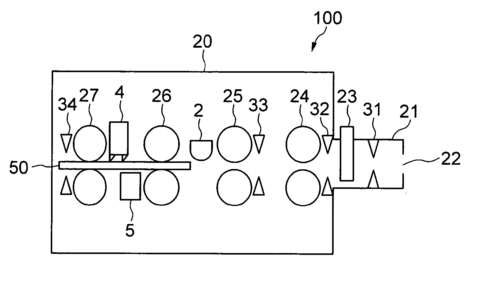
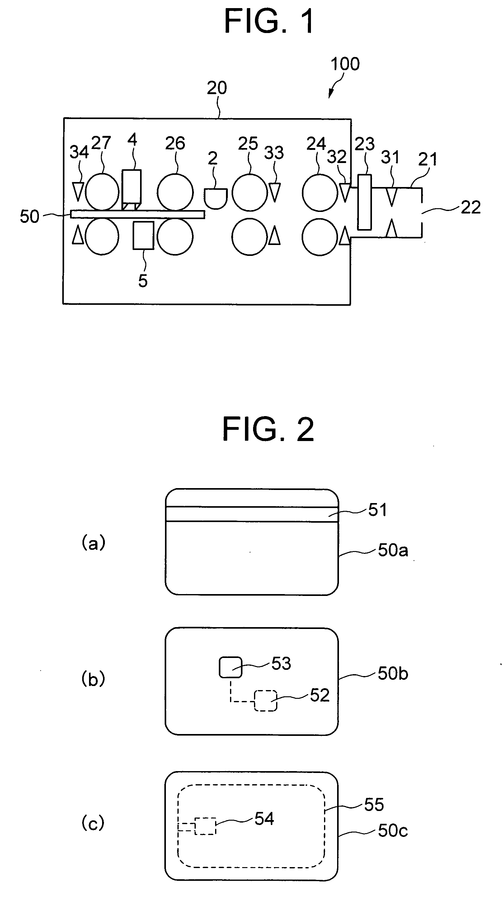
[0044]FIG. 1 is a diagram showing the general structure of a card processing device in an embodiment of the present invention. Referring to FIG. 1, the numeral 100 is a card processing device mounted, for example, on an ATM. The numeral 50 is a card processed by the card processing device 100. This card may be one of a magnetic card 50a with a magnetic stripe 51 such as the one shown in FIG. 2(a), a contact IC card 50b with an IC chip 52 and an IC terminal 53 such as the one shown in FIG. 2(b), and a non-contact IC card 50c with an IC chip 54 and an antenna 55 such as the one shown in FIG. 2(c). As just described, the card processing device 100 is a device capable of processing both the magnetic card 50a on which magnetic information is recorded and the IC cards 50b and 50c on which magnetic information is not recorded. The cards 50a-50c are of almost the same size.

[0045] The numeral 20 is the main body of the card processing device 100, the numeral 21 is a card insertion unit prov...


PUM


Abstract

A card processing device (100) that handles a magnetic card and an IC card wherein, when a card (50) is taken into a main body (20) and if the card is a magnetic card, the inserted card (50) is taken in by intermittently transporting the card to a predetermined position and, after that, by continuously transporting the card and, if the card is an IC card, the inserted card (50) is taken in by continuously transporting the card. When the card (50) is ejected out of the main body (20) and if the card is a magnetic card, the card is ejected by continuously transporting the card to a predetermined position and, after that, by intermittently transporting the card and, if the card is an IC card, the card is ejected by continuously transporting the card.

Description

TECHNICAL FIELD [0001] The present invention relates to a card processing device that processes a card on which magnetic information is recorded and a card on which magnetic information is not recorded. BACKGROUND ART [0002] Some card processing device mounted on a bank's automated teller machine (hereinafter called ATM) processes both a magnetic card on which magnetic information is recorded and an IC card on which magnetic information is not recorded (for example, see JP-A-5-101230 (prior art 1) and Japanese Patent Application No. 3326351 (prior art 2)). When a magnetic card is inserted from the card insertion slot of this card processing device, the magnetic information recorded in the magnetic stripe on the card is read by the magnetic head while the magnetic card is transported by the transport means, such as a motor and rollers, at a constant speed. When an IC card is inserted from the card insertion slot, the IC card is transported by the transport means described above to a ...

Claims


Application Information

Patent Timeline
Patent Type & Authority Applications(United States)
IPC IPC(8): G06K13/00G06K7/00G06K13/08G06K13/077G07D9/00G06K13/06G06K17/00G07F19/00
CPCG06K7/0004G06K13/0843G07F19/20G07F19/201
Inventor TADAMASA, AKIHIRO
Owner HITACHI OMRON TERMINAL SOLUTIONS CORP
Why Eureka
Try Eureka