
Optical add/drop multiplexers

Inactive Publication Date: 2007-04-05
PROXIMON FIBER SYST
View PDF3 Cites 0 Cited by
  • Summary
  • Abstract
  • Description
  • Claims
  • Application Information

AI Technical Summary

Benefits of technology

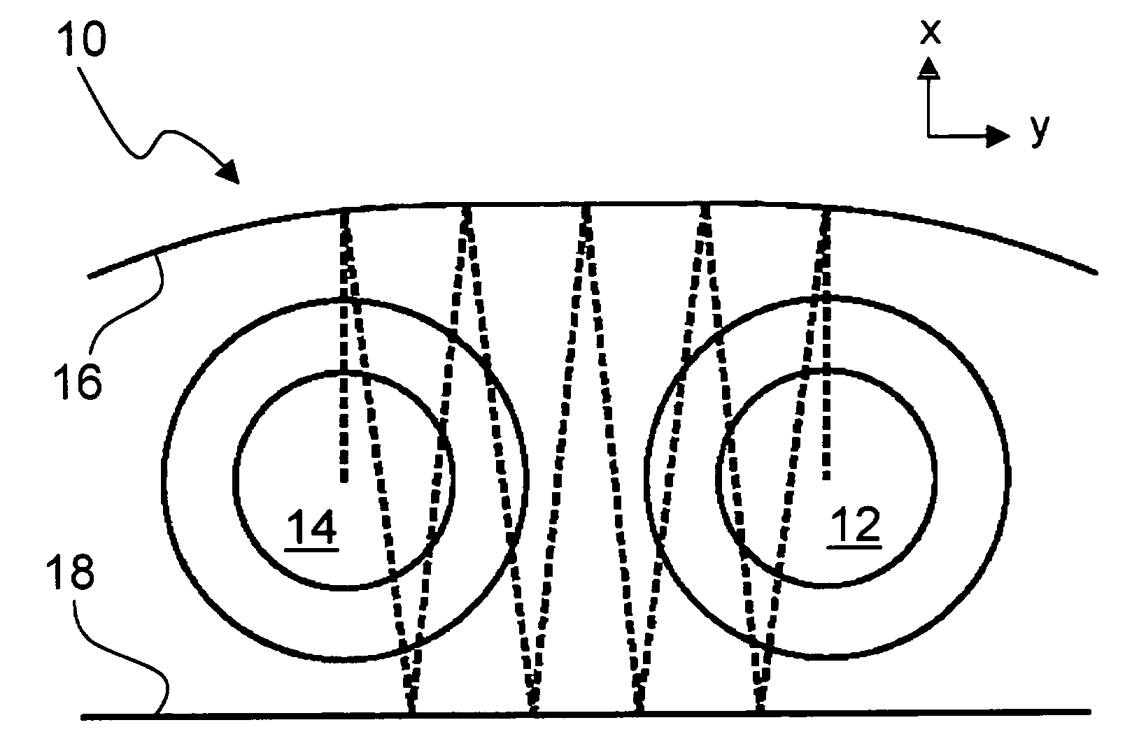
[0018] Hence, the present invention is based upon an understanding that by selecting a well-defined, curved shape for at least one of the reflecting elements that constitute the external resonator or by providing suitable refractive portions or components, it is possible to create resonator modes that may couple light to, or be excited from, a deflecting portion of a first waveguide and simultaneously be excited from, or couple light to, a deflecting portion of a second waveguide, wherein the waveguides define a geometrical plane substantially parallel to the resonator mirrors. Hence, according to the present invention, the coupling between the waveguides is achieved while having the second waveguide positioned well outside the geometrical plane defined by the protruding lobes from deflecting portions of the first waveguide.
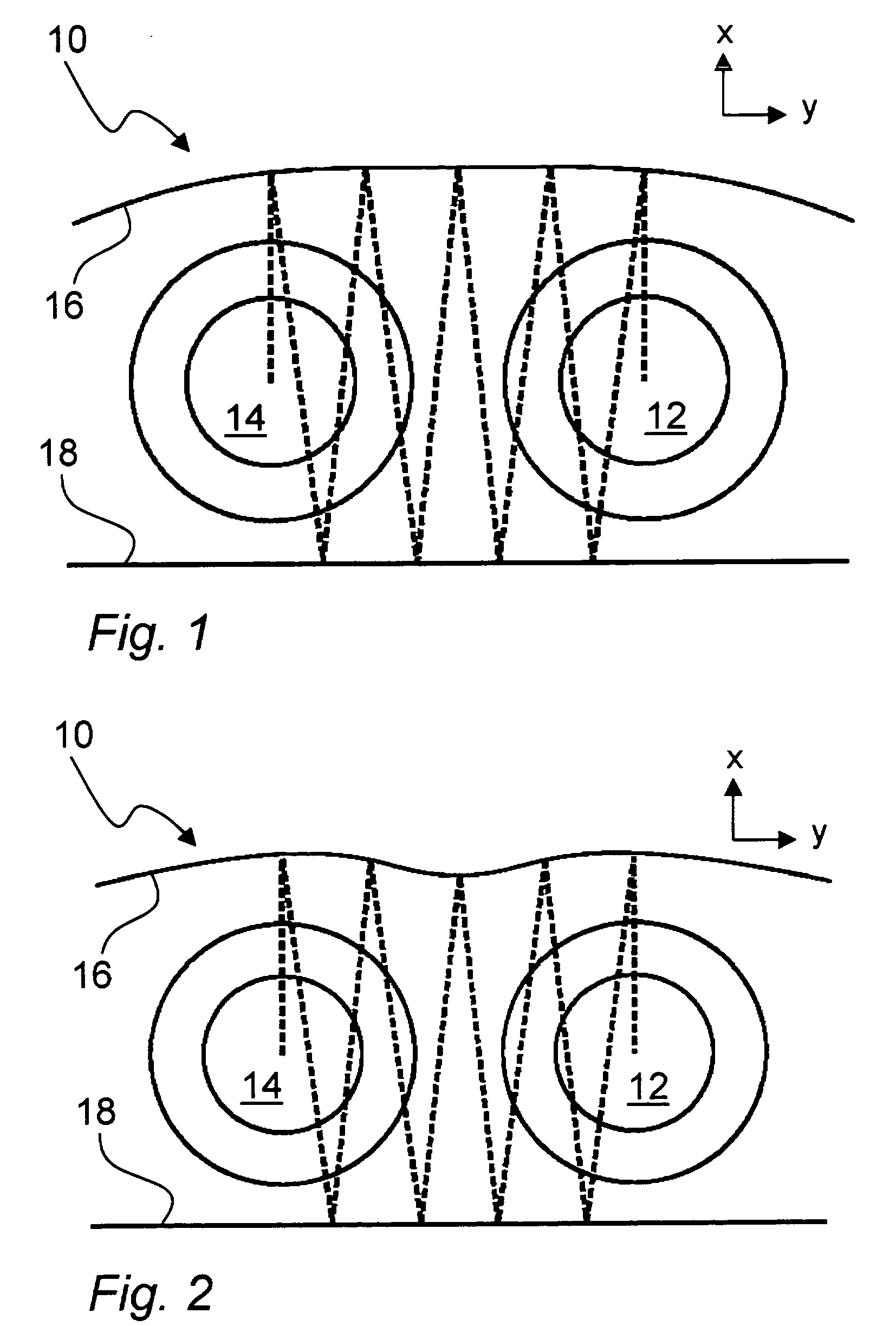
[0019] Thus, in coarse terms, the present invention proposes to couple light between waveguides by extracting light from the first waveguide in a first direction, generally perpendicular to the propagation direction for light within the waveguide, such that the extracted light enters a mode in the external resonator. The external resonator is designed such that the mode(s) have an extension in a lateral direction, being more or less perpendicular to both the first, extraction direction and to the propagation direction of light within the waveguide. Further, at least one mode of the external resonator overlaps with a corresponding coupling portion of the second waveguide, said second waveguide being located adjacent the first waveguide. The lateral extension of the (bound) mode in the external resonator is obtained by having at least one of the resonator mirrors appropriately curved or by incorporating refractive elements or portions in the external resonator. In this manner, it is not necessary for the two waveguides to be placed next to each other on a line going from one resonator mirror to the other (i.e. in the direction of the protruding light lobes).
[0020] Hence, the inventive design enables a new coupler geometry, wherein light is resonantly coupled out from the first waveguide and into a resonator mode, said resonator mode also overlapping with the second waveguide thereby enabling resonant coupling of light into said second waveguide. For the same FSR of the external resonator, the inventive geometry allows the waveguides (e.g. optical fibers) to be of twice the diameter or size compared to the prior art.
[0023] The external resonator according to the present invention will typically exhibit several resonant modes, meaning that the behavior and the wavelength characteristics will be more complex than if only one single mode were supported. However, it can be shown that it is possible to make all resonator modes except one lossy. Thereby, although light from the deflecting portion of the first waveguide (fiber) within a particular wavelength range may excite such lossy resonator mode, only a very small and in practice negligible amount of light will couple to the resonator mode, since the build-up of a resonance is prevented by the losses.
[0024] Preferably, a blazed Bragg grating is used for deflecting light out from the fiber core. It is particularly preferred to use an apodized, blazed Bragg grating for this purpose. Such apodized grating preferably has the properties of a band pass filter approaching a tophat spectral characteristic. In the spatial domain, such filter transforms into a sinc-like function. Normally, only a portion of the sinc-function is used, since it is often the desire to keep the length of the deflecting grating to a minimum. This may be accomplished by truncating the side lobes of the sinc-like function and weighing it with a Kaiser window function. The use of an apodized Bragg grating provides good suppression of group delay ripple for a wide wavelength range.
[0026] Preferably, the separation between the reflecting elements of the external resonator is controllable, e.g. by means of electrostatic tuning. Improved tuning capabilities may be obtained for an embodiment in which at least one of the reflecting elements is divided into several reflective subsections, wherein each subsection is individually controllable with respect to the second, opposing reflective element of the resonator. In this manner, it is possible to control the efficiency of coupling from the first waveguide to the second waveguide, and to compensate for any imperfections in the shape of the resonator.

Problems solved by technology

Despite the apparent advantages of ROADMs in network design, these devices have not yet become widely used.
One main reason may be the cost currently associated with the construction and implementation of such devices, but there are also other issues.
Most often, this is considered from a power distortion point of view, but phase distortion, which may cause anomalous dispersion, can be equally detrimental.
For example, the loss suffered by the express channels is relatively high and the tuning mechanisms are sensitive to vibrations.
It has also proven to be very complicated and costly to provide for hitless tuning in TTF-based ROADMs.
One major drawback of FBG-based three-port filters is that the optical circulators introduce significant loss.
The circulators are also associated with a high cost.
It has also proven to be problematic to make the FBGs tunable over the entire wavelength range of interest, and to make the filters hitless during tuning.
One major drawback associated with this approach is that the demultiplexing / multiplexing operations introduce significant loss.
Moreover, the required components are typically costly.
The loss suffered in a device according to this approach is significant, and typically amplifiers need to be introduced.
The large number of components involved also make this an expensive and bulky approach.
Light of a wavelength that is in resonance with the external resonator will, after one round trip in the resonator, interfere constructively with subsequently deflected light of the same wavelength.
Hence, it is clear that the small separation required between the mirrors of the external resonator leads to quite some challenges from a manufacturing standpoint.

Method used


Image

  • Optical add/drop multiplexers
  • Optical add/drop multiplexers
  • Optical add/drop multiplexers

Examples


Embodiment Construction

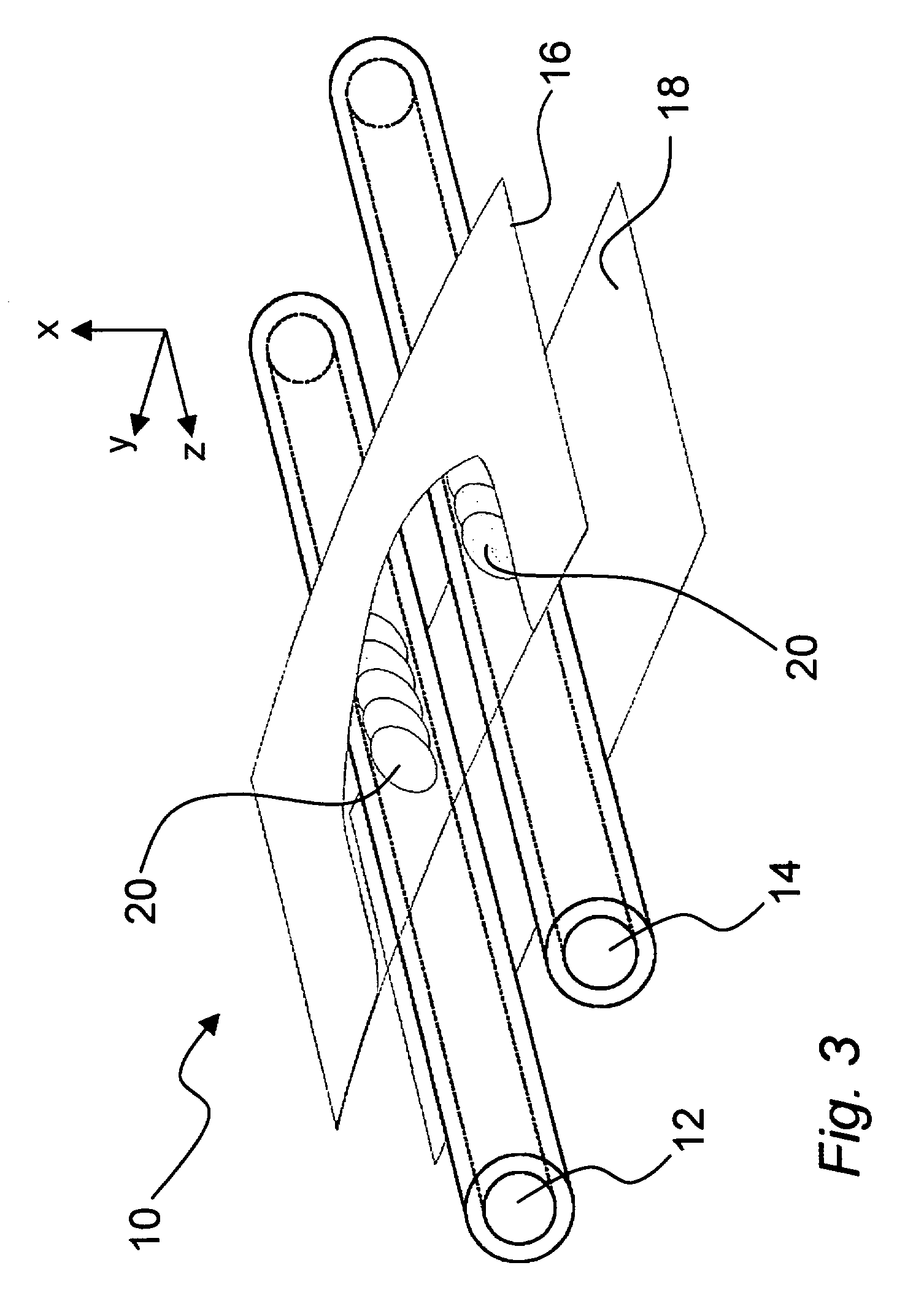
[0034]FIG. 1 schematically shows an optical coupler 10 according to the present invention. The coupler comprises a first and a second waveguide 12, 14, and an external resonator defined by a first and a second mirror 16, 18. It should be understood that only those parts required for explaining the principles of the invention are shown, additional parts typically being required to implement an actual working device, as will be appreciated.

[0035] By way of introduction, some generic principles of the invention will be described. In order to make the description even more clear, a Cartesian coordinate system (x, y, z) is defined, such that for the present invention the propagation direction of light in the waveguides 12, 14 is along the z-direction, the separation between the waveguides is along the y-direction, and the separation between the resonator mirrors 16, 18 is along the x-direction. This is most easily seen by referring to the figures.

[0036] A fundamental difference between...


PUM


Abstract

A spectrally selective optical coupler is disclosed, comprising a first and a second waveguide; an external resonator defined by at least a first and a second mirror; and a respective deflecting portion in each of said waveguides for coupling light between the waveguide and the external resonator. The waveguides are arranged between the mirrors adjacent to each other in a plane that is generally parallel to said mirrors; and the external resonator is designed such that a resonant mode within the external resonator overlaps the deflecting portion in the first and the second waveguide. The inventive coupler solves some limiting geometrical problems encountered in the prior art. A lateral extension of a mode in the external resonator overlapping both waveguides is obtained using a curved resonator mirror or refractive elements or portions within the resonator.

Description

TECHNICAL FIELD [0001] The present invention relates to the general field of optical couplers. More particularly, the invention relates to optical couplers for use as optical add / drop multiplexers. TECHNICAL BACKGROUND [0002] Optical add / drop multiplexers (OADMs) is typically considered to be a generic term for devices that have the functionality of selecting a subset of optical channels from an incoming optical fiber, or other optical transport medium, and dropping the light carrying these channels into a second optical fiber, and adding a subset of channels from a third optical fiber to an output fiber carrying the undropped optical channels from the incoming fiber. In other words, OADMs are used for adding, dropping and exchanging optical channels in wavelength division multiplexing (WDM) systems. In WDM networks, each optical channel is designated a different wavelength, referred to as a wavelength channel. The introduction of OADMs in optical networks enables new and more effic...

Claims


Application Information

Patent Timeline
IPC IPC(8): G02B6/26G02B6/42
CPCG02B6/29358G02B6/29383G02B6/29395H04J14/0206H04J14/021H04J14/06
Inventor SAHLGREN, BENGTPEJNEFORS, JOHANHELMFRID, STEN
Owner PROXIMON FIBER SYST
Learn More