
Silent chain

Inactive Publication Date: 2010-08-26
TSUBAKIMOTO CHAIN CO
View PDF6 Cites 8 Cited by
  • Summary
  • Abstract
  • Description
  • Claims
  • Application Information

AI Technical Summary

Benefits of technology

[0005]In this invention, inward flexion of the chain, i.e., flexion of a link plate toward the inside of the loop formed by the chain, is limited by the use of cushion pads in order to suppress chordal vibration. The suppression of chordal vibration is achieved without impairing freedom in the design of the V-shaped teeth and the cushion pads. Flexion of the chain toward the outside of the loop can also be restricted, drive vibration can be absorbed, and a positive supply of lubricating oil to the components of the chain can be maintained.
[0014]In accordance with still another aspect of the invention, each cushion pad is formed of a material which retains lubricating oil. Because the protruding parts of the cushion pads are sandwiched between pairs of link plates in adjacent rows, they are repeatedly compressed and expanded during operation of the chain. Consequently, these sandwiched parts of the cushion pads exert a pumping effect, supplying lubricating oil retained inside the cushion pads to various components of the chain, and maintaining smooth flexion of the chain. In particular, since the cushion pads are provided in the flank regions of the link plates between their front and rear V-shaped link teeth, lubricating oil is positively supplied to the V-shaped link teeth, where they engage with sprocket teeth.

Problems solved by technology

Thus, when a link plate is formed of hard material such as steel, vibration and noise are generated due to contact between the protrusions and the shoulders of adjacent toothed link plates or guide links.
In addition, because the protrusions typically have low strength, the chain is subject to fatigue failure due to repeated contact with the shoulders of adjacent toothed link plates or guide links.

Method used


Image

  • Silent chain
  • Silent chain
  • Silent chain

Examples


first embodiment

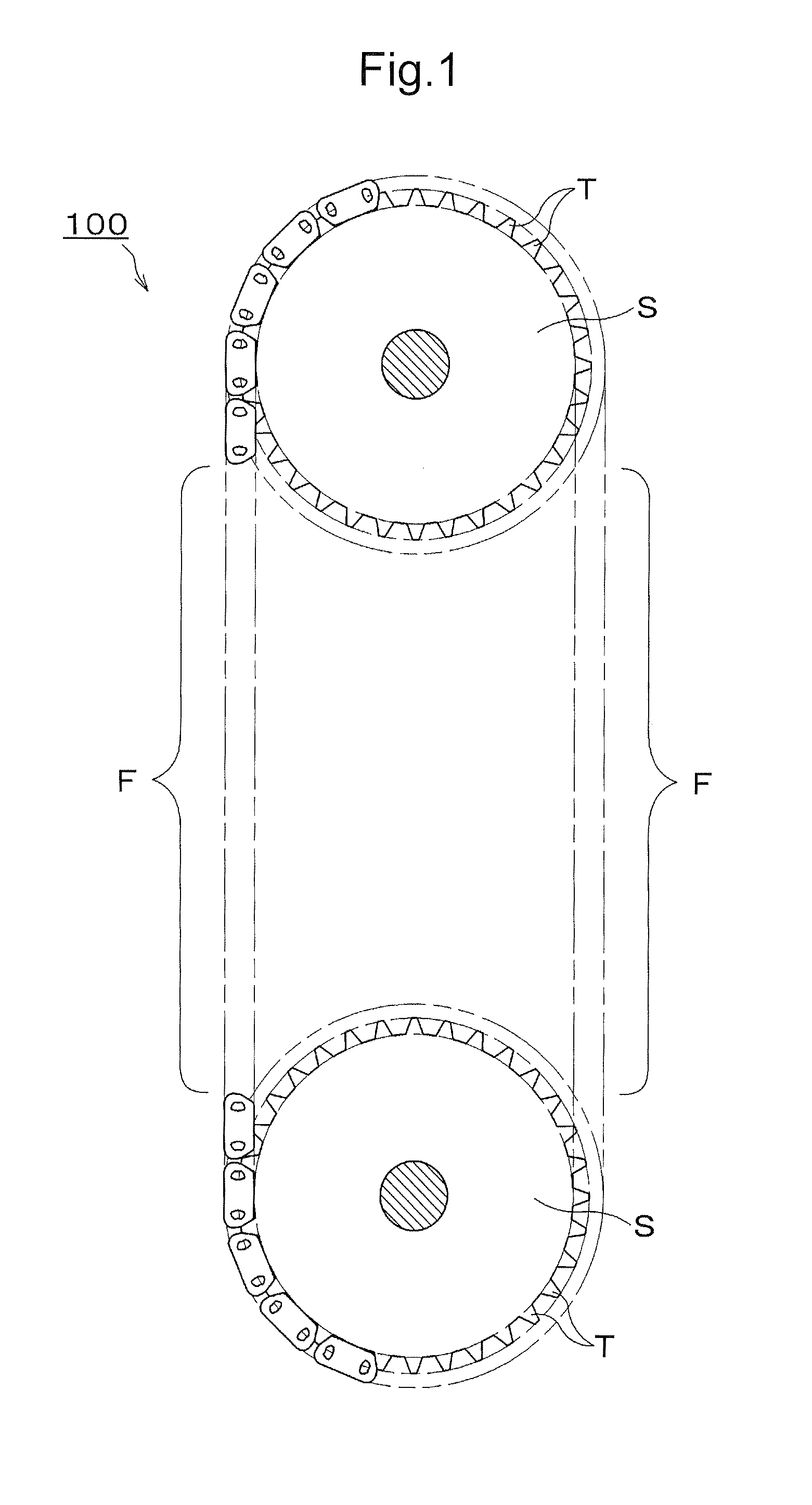
[0029]A silent chain 100, according to the invention, is depicted in FIGS. 1-4. The chain is engaged with sprockets S as shown in FIG. 1, one of which is driving sprocket and the other of which is a driven sprocket.

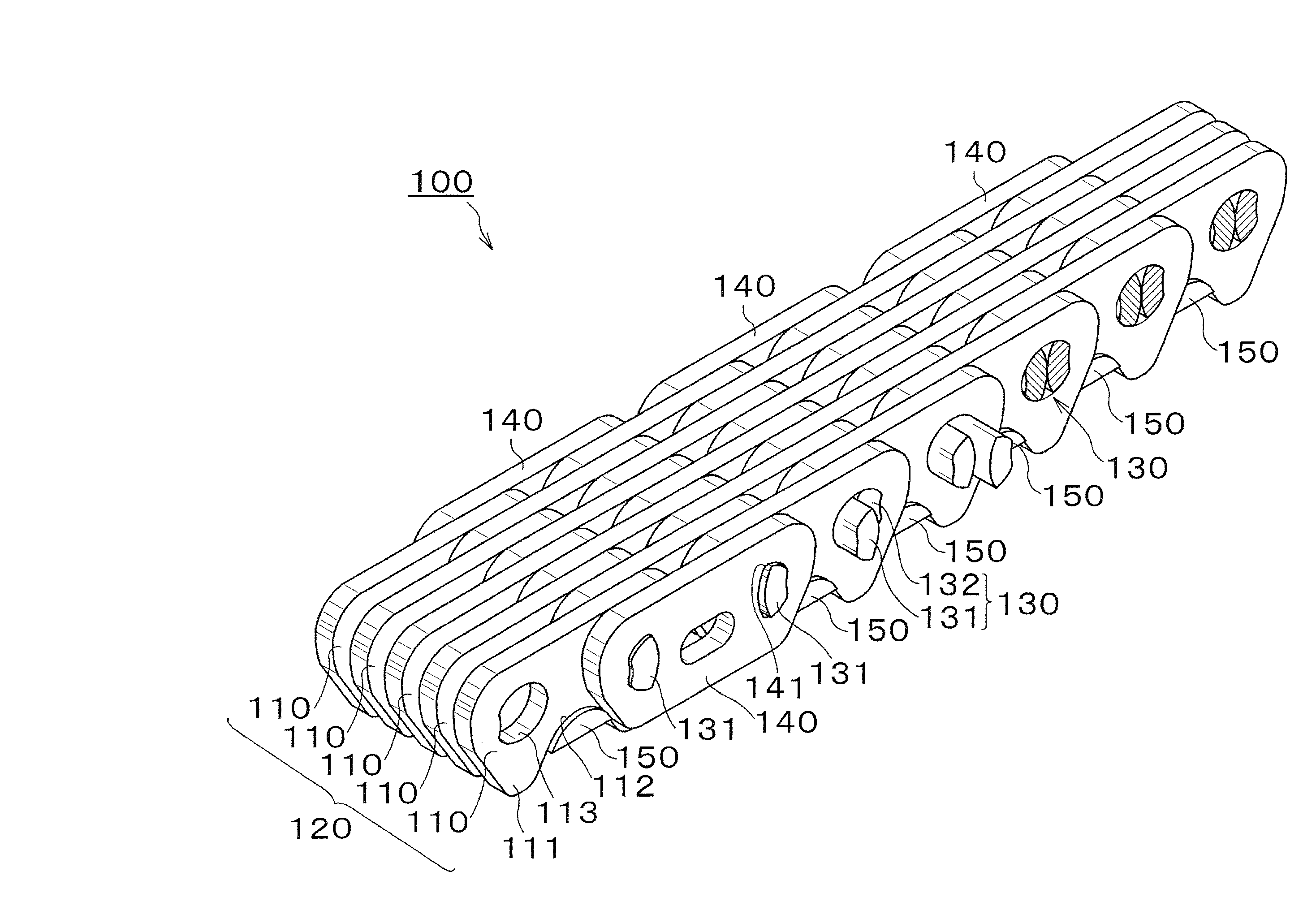
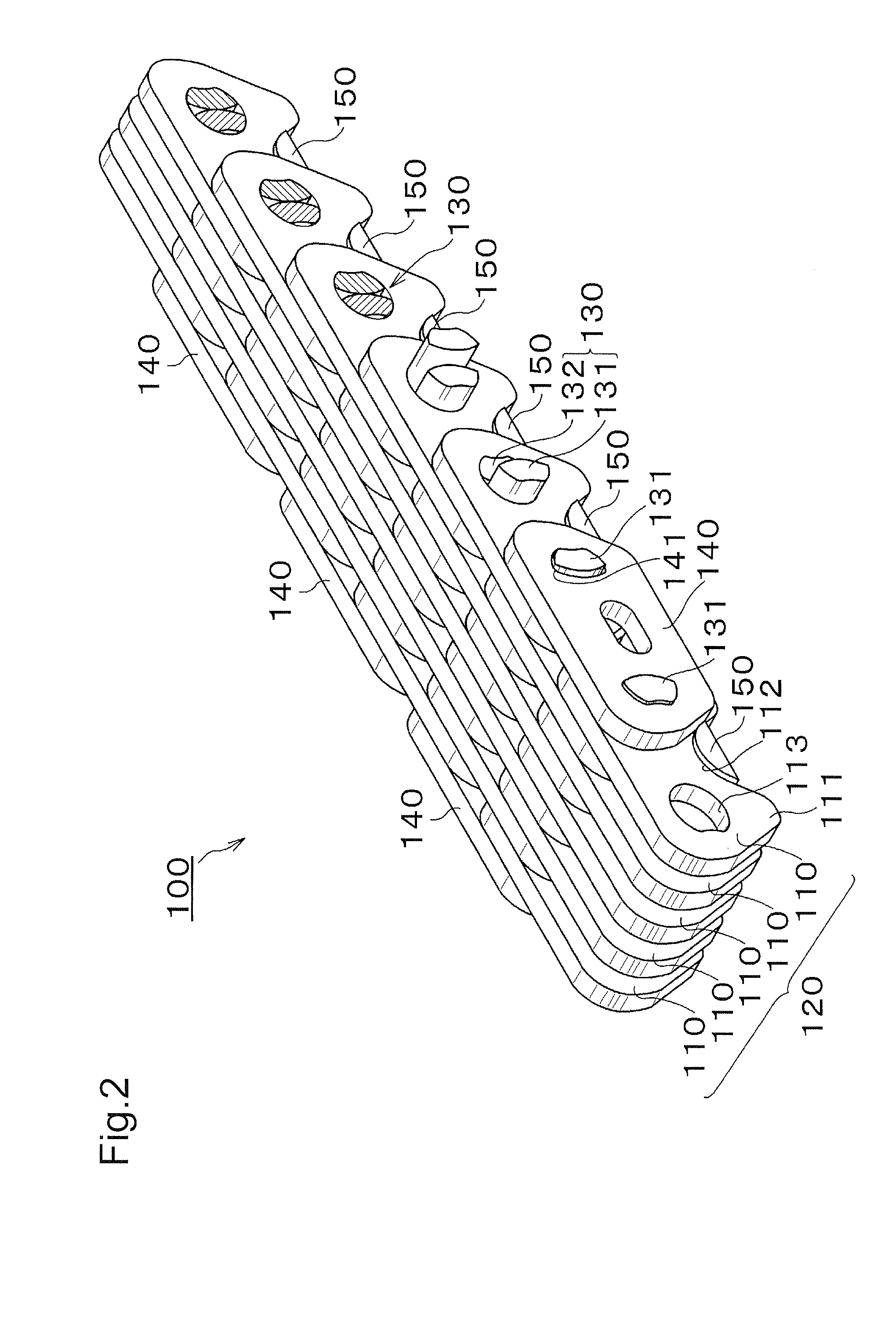
[0030]As shown in FIGS. 2 and 3, the silent chain 100 is formed by interleaved link rows 120, each of which extends in the direction of the width of the chain and is composed of link plates 110, each having front and rear, V-shaped, teeth 111, which engage teeth T (FIG. 1) of the sprockets S. Flank regions 112, between the front and rear V-shaped teeth 111, are continuous from the front V-shaped tooth to the rear V-shaped tooth. These flank regions are opposed to, and receive, sprocket teeth T without contacting the sprocket teeth. Front and rear connecting pin holes 113 are formed adjacent the respective front and rear teeth 111. The front pin holes in a row are aligned with one another in the direction of the width of the chain, as are the rear pin holes. The interleave...

second embodiment

[0040]In the second embodiment, the cushion pad 250 in each row 220 of link plates 210 is elongated in the widthwise direction of the chain, and is continuous over the length of the row. Each cushion pad 250 is adhered to flank regions 212 of a plurality, and preferably all, of the toothed link plates 210 in its row.

[0041]The portions 251 of a cushion pad that extend between adjacent plates in the row in which the cushion pad is situated are engageable with link plates in adjacent rows and also, in the case of a cushion pad in a non-guide row, with guide plates in adjacent guide rows.

[0042]In the silent chain 200, the cushion pads 250 which extend through the flank regions 212 of the link plates 210, include parts 251 that extend widthwise beyond the link plates 210. The parts 251 that are disposed in the spaces between adjacent link plates 210 between a link plate 210 and a guide plate 240, restrict inward flexion of the chain, and suppress chordal vibration of the free span region...


PUM


Abstract

In a silent chain, cushion pads are provided in the inner flank regions of at least every second link row. These cushion pads restrict inward flexion of the chain and reduce vibration of the free span regions of the chain. The cushion pads can be individual pads each associated with a link plate, or elongated pads each associated with a row of link plates. In either case, side parts protruding toward the outside of the loop formed by the chain can also restrict outward flexion of the chain.

Description

CROSS-REFERENCE TO RELATED APPLICATION[0001]This application claims priority on the basis of Japanese patent application 2009-041838, filed Feb. 25, 2009. The disclosure of Japanese application 2009-041838 is hereby incorporated by reference.FIELD OF THE INVENTION[0002]This invention relates to a silent chain for use in a chain transmission, a transfer conveyor, or the like. It relates more specifically to a silent chain comprising an elongated series of interleaved rows of link plates, each link plate having front and rear V-shaped teeth for engagement with sprocket teeth, a flank region between the front and rear V-shaped teeth for receiving sprocket teeth without contacting the sprocket teeth, and front and rear connecting pin holes formed in each link plate respectively adjacent the front and rear V-shaped teeth, the V-shaped teeth being arranged in parallel rows extending in a direction of the chain width perpendicular to the direction of elongation of the chain, and connecting...

Claims


Application Information

Patent Timeline
IPC IPC(8): F16G13/18F16G13/07F16G13/02F16G13/08
CPCF16G13/04F16G13/18F16G13/08
Inventor KABAI, TSUYOSHIHAMAGUCHI, SHUUJIMORIMOTO, TAKAYUKI
Owner TSUBAKIMOTO CHAIN CO
Learn More