Wide-bandwidth balanced transformer

Inactive Publication Date: 2007-04-05
GRUCHALLA MICHAEL E
View PDF2 Cites 5 Cited by
  • Summary
  • Abstract
  • Description
  • Claims
  • Application Information

AI Technical Summary

Benefits of technology

[0024] The present invention relates to a device providing impedance transformation and transformation between single-ended and balanced circuits over a bandwidth of as much as 20 octaves while also providing low insertion loss and very low phase and amplitude ripple in the pass band. The present invention effects both impedance transformation and transformation between single-ended and balanced circuits of arbitrary impedances while providing low loss and very wide-bandwidth by means of novel arrangements of coaxial transmission-line structure or sections and magnetic elements.
[0026] Whereas the coaxial transmission-line structure provides a very well-defined bounded-wave structure for communication of high-frequency signals, operation to very high frequencies is provided according to the present invention comprising coaxial-line structures. Further, whereas the conductors of conventional transmission lines, for example, the two conductors of coaxial and parallel-conductor transmission lines, are each continuous conductors, these conductors are simultaneously applied as conventional transformer windings to also provide low-loss, low-frequency operation in the present invention. Therefore, the present invention significantly improves the bandwidth and loss over the prior art of impedance transformation between two arbitrary impedances and in the transformation between single-ended and balanced circuits.

Problems solved by technology

In the prior art, it is problematic to provide both impedance transformation between two arbitrary impedances and single-ended-to-balanced transformation.
Specifically, low-loss transformation of impedances is typically limited to ratios related by the squares of whole numbers.
However, a transformation such as 50 ohms to 100 ohms, an impedance ratio of the square-root of 2, is not typically provided in low-loss devices of the prior art.
In prior-art devices providing such a transformation, bandwidth is limited to only several octaves and insertion loss is comparatively high.
The devices of prior art cannot satisfy the requirements to provide transformation between single-ended and balanced circuits in a device that also provides impedance matching between two arbitrary impedances over a very wide-bandwidth and with very low loss.
A serious disadvantage of the prior art taught by Yusaku is that only a 1:1 impedance transformation is provided.
Another serious disadvantage of the prior art taught by Yusaku is that its construction is generally limited to parallel-wire transmission-line sections.
Such transmission line constructions are not totally bounded-wave electromagnetic configurations and therefore are severely limited in maximum operating frequency where the length of such line structure is comparatively long or where such line section is in the vicinity of other circuit elements or physical features of the system in which incorporated.
A serious disadvantage of the prior art taught by Buschbeck is that only a 4:1 impedance transformation is provided, for example, 50 ohms to 200 ohms or 100 ohms to 25 ohms.
Another serious disadvantage of the prior art taught by Buschbeck is that it must be applied where the various feature lengths are ¼ wavelength.
Accordingly, the prior art taught by Buschbeck is limited to effectively single-frequency or very narrow-band operation.
Whereas the device taught by Guanella is substantially electrically equivalent to that taught by Buschbeck, the device taught by Guanella is also limited to impedance transformation values that are the squares of whole numbers, 1:1 and 4:1 for example.
This is a serious deficiency where matching of impedances having arbitrary impedance ratios is required.
A serious deficiency of the prior art taught by Sevick is that the physical geometry does not present a balanced coupling to free space and therefore cannot provide high-performance balanced operation because of the single-ended parasitic free-space coupling.
A serious deficiency in the prior art taught by Sevick is that the quadrifilar and bifilar winding configurations are not well defined in impedance and are not fully bounded-wave electromagnetic structures.
Therefore, the configuration taught by Sevick is severely limited in operating frequency where the line lengths are comparatively long or where such line sections are in the vicinity of other circuit elements or physical features of the system in which incorporated.

Method used


Image

  • Wide-bandwidth balanced transformer
  • Wide-bandwidth balanced transformer
  • Wide-bandwidth balanced transformer

Examples


Embodiment Construction

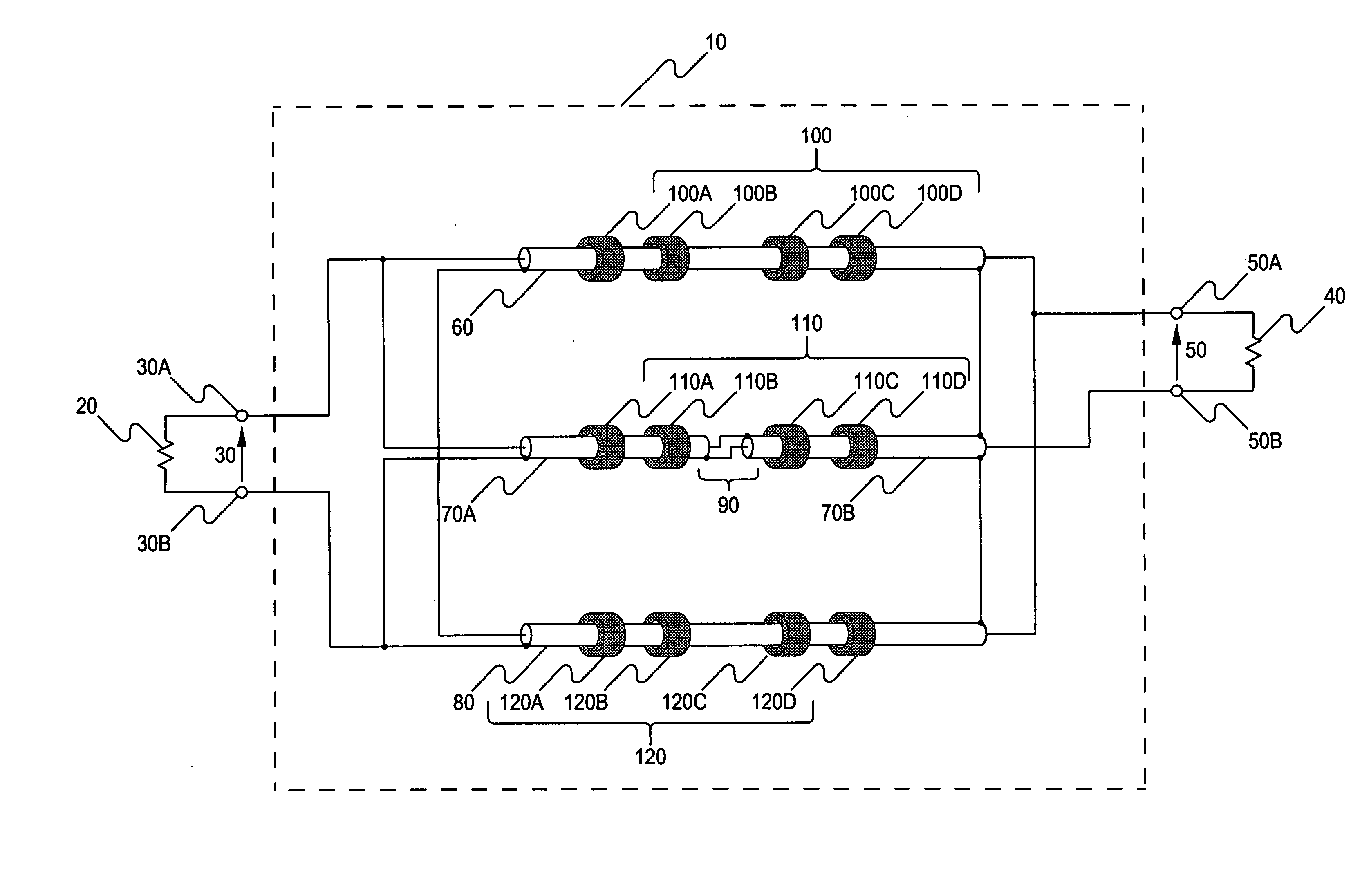
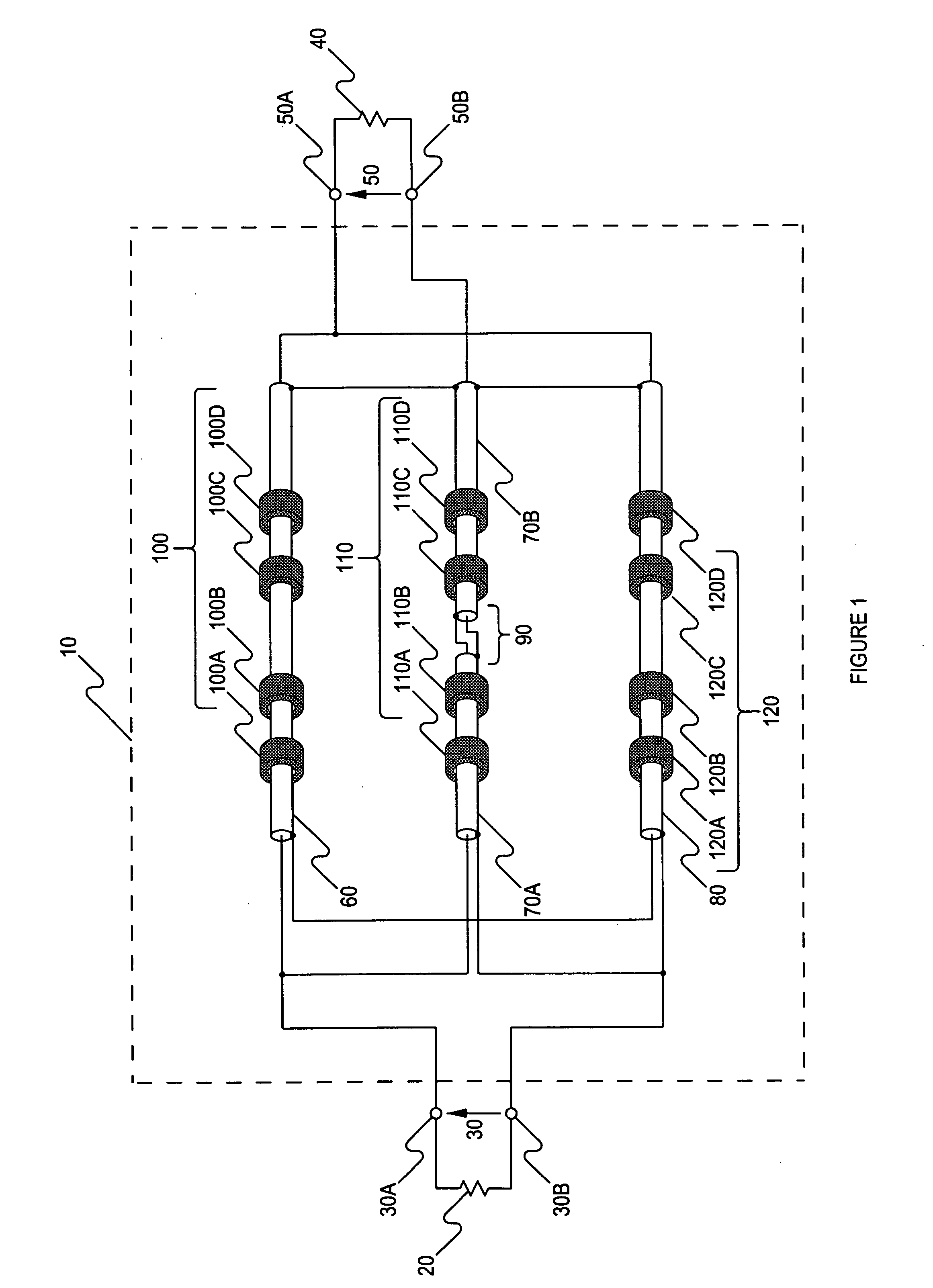
[0046] The embodiment of the present invention illustrated in FIG. 1 comprises a novel connection of a plurality of transmission-line sections or means and a plurality of magnetic mechanisms or means providing impedance transformation between two arbitrary impedances, where either or both of the two impedances may be single-ended with respect to ground, floating with respect to ground, or balanced to ground, in a physical topology providing very wide-bandwidth, low-loss operation. Such impedance transformation in combination with means or mechanism to match between single-ended, floating, and balanced circuits with very wide-bandwidth, low loss operation represent significant and novel improvements provided by the present invention over transformation means of the prior art.

[0047] With reference to FIG. 1, transformation means or device 10 provides impedance matching between an impedance 20 at port 30 and impedance 40 at port 50. Port 30 comprises terminals 30A, 30B between which i...


PUM


Abstract

The present invention comprises novel means and apparatus which provide both impedance matching of arbitrary impedances and transformation between single-ended, floating, and balanced circuits over very wide operating bandwidths with very low excess loss and very low phase and magnitude ripple in the pass band. The present invention can provide high-performance matching, for example from a 50-ohm single-ended system to a 100-ohm balanced system over a bandwidth of 10 kHz to 10 GHz with an excess loss of less than nominally 1 dB and a bandpass magnitude ripple of less than ±0.5 dB. The present invention also provides precision low-loss power division over very wide-bandwidth. The novel means, according to the present invention, can utilize commonly available materials and can be optimized for specific applications to tailor performance to specific needs and to simplify assembly and reduce cost.

Description

FIELD OF THE INVENTION [0001] The present invention relates to a wide-bandwidth transformer device. BACKGROUND OF THE INVENTION [0002] Wide-bandwidth transformer devices are very common in the prior art for such applications as providing impedance matching between the source and load in radio-frequency (“RF”) applications. Balanced transformer devices (“balun”) are also common in applications where a balanced signal is required from a single-ended source and where a balanced signal is to be delivered to a single-ended load. In the prior art, it is problematic to provide both impedance transformation between two arbitrary impedances and single-ended-to-balanced transformation. Specifically, low-loss transformation of impedances is typically limited to ratios related by the squares of whole numbers. The following examples are easily provided with devices of the prior art: a 1:1 transformation, the square of 1, and a 4:1 transformation, the square of 2. However, a transformation such a...

Claims


Application Information

Patent Timeline
IPC IPC(8): H03H7/38
CPCH01F3/10H01F17/06H01P5/10
Inventor GRUCHALLA, MICHAEL E.
Owner GRUCHALLA MICHAEL E
Why Eureka
Try Eureka