[0018] It is an object of the present invention to enhance and improve the efficiency and safety of conventional direct expansion,
geothermal heating / cooling system, sub-surface, vertically oriented,
copper tubing installations, as well as more horizontally oriented lake installations. This is accomplished by providing a wide (relative to the
diameter of the borehole / well), weighted, and elongated, encasement
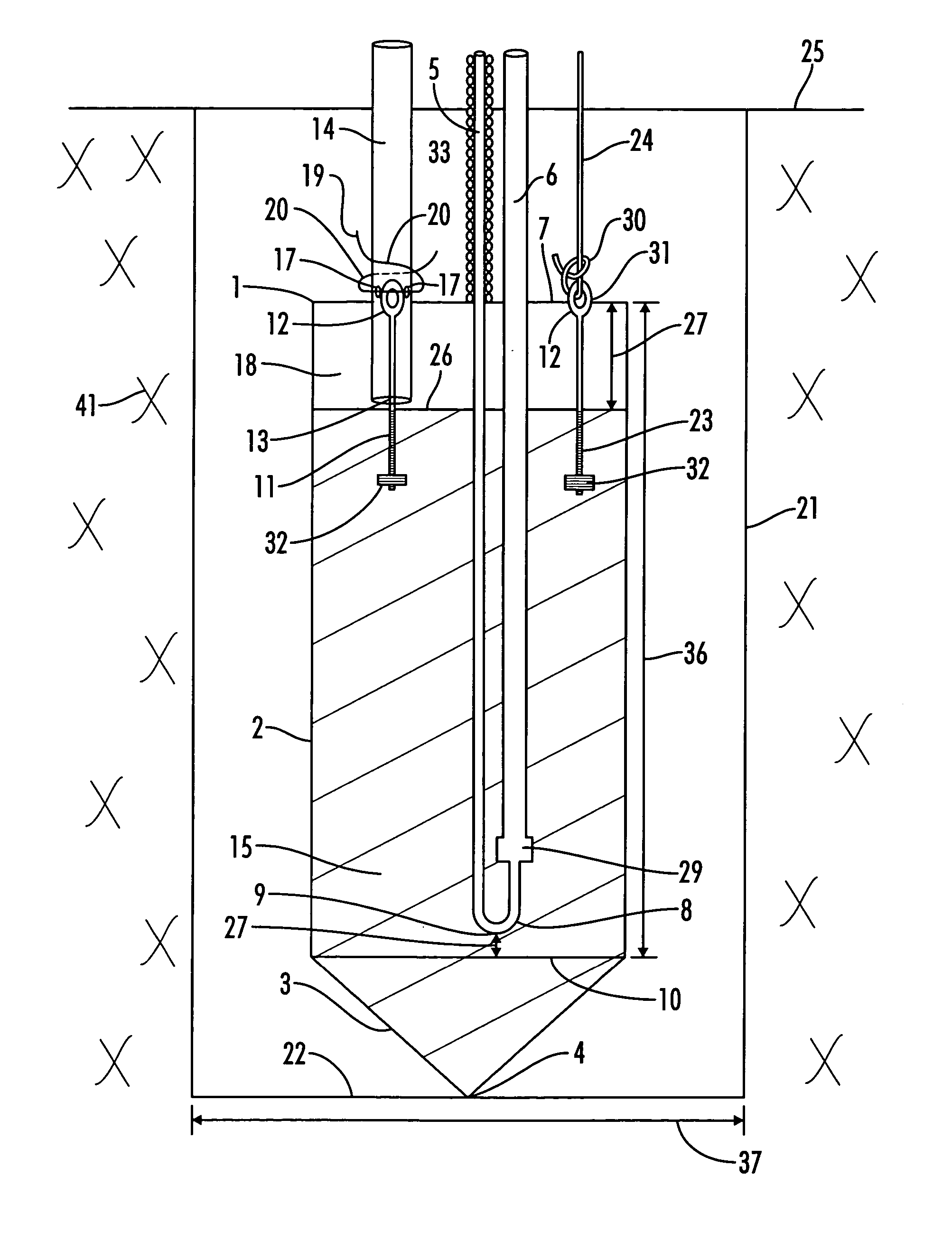
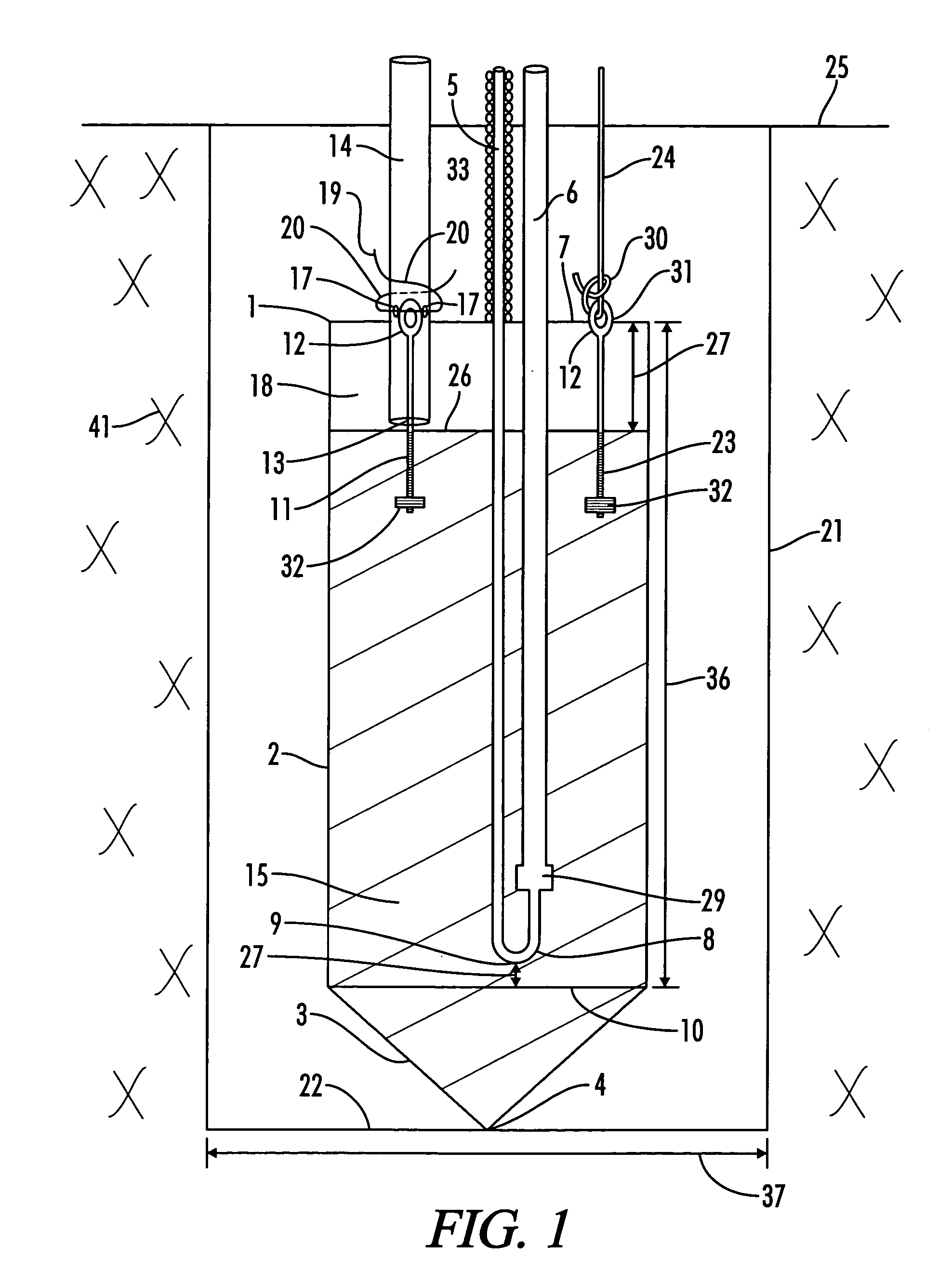
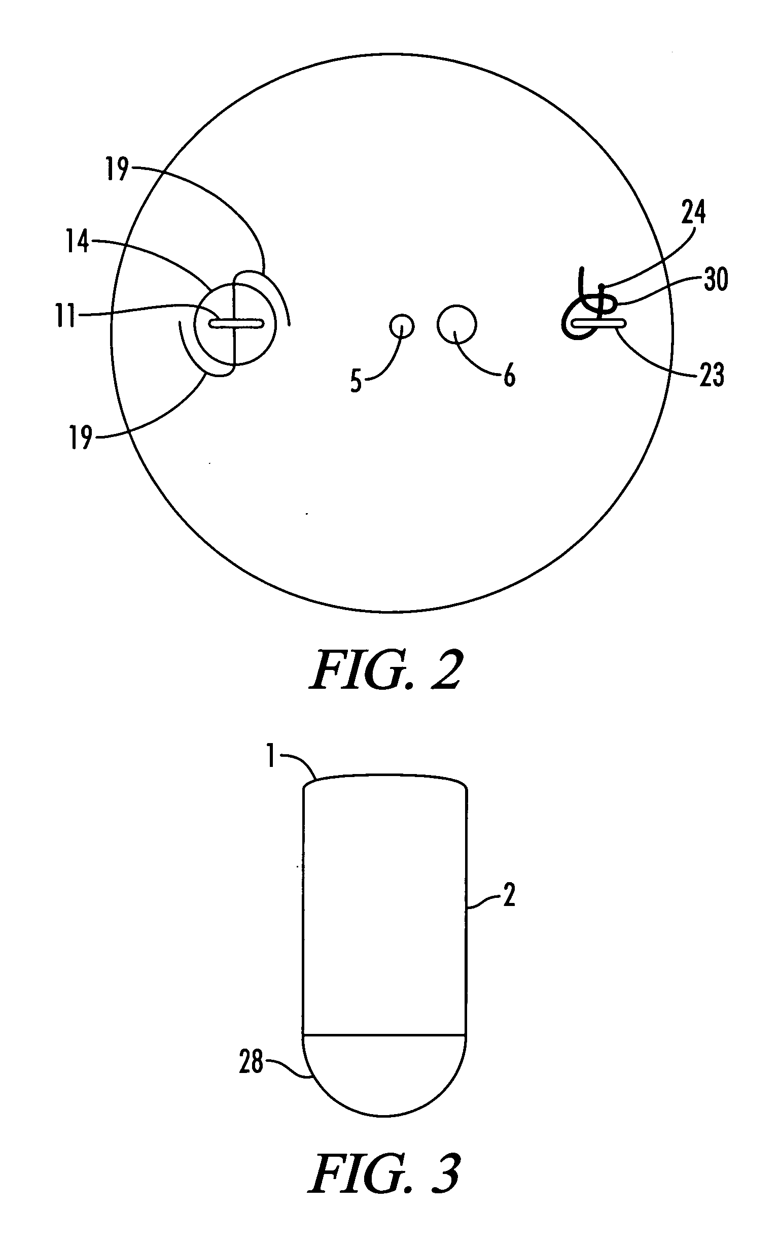
assembly comprising an encasement tube with a flat top and with at least one of a rounded and a cone shaped bottom end, within which to insert the copper tubing and the trimmie tubing as it is being lowered into the well / borehole. This configuration also allows the installer to easily pull a loosely attached trimmie tube loose from the tube without damaging the copper refrigerant transport tubing. Such an encasement
assembly, because a preferred embodiment has dimensions similar to a
torpedo, can sometimes be referred to as a “
torpedo” design.
[0019] The encasement assembly of the present invention is comprised of an encasement tube, or the like, made of steel, PVC, copper,
metal, plastic, or the like, that is longer than it is wide. The encasement tube has a main body portion with a flat upper top portion. The width of the main body portion, for use in a 4.5 inch
diameter well / borehole for example, would preferably be in the 2.5 inch to 3 inch range, while the width for use in a larger
diameter well / borehole could be larger, with preferably at least a 1 inch diameter clearance. The length of the encasement tube would be at least longer than the width of the well / borehole, so as to prevent the encasement tube from turning sideways in the well. The length should preferably be at least longer than the U-bend portion of the copper refrigerant transport tubing, and should be long enough, so that when combined with its contents, will achieve the desired weight. The weight of the completed encasement tube should preferably be in the 10 pound to 40 pound range. The heavier the encasement (25 to 40 pounds), the easier it is to install the copper tubing in a water-filled well. The lighter the encasement tube (10 to 20 pounds), the easier it is to pull out the copper tubing for any necessary repairs via pressure testing prior to grouting.
[0020] The encasement tube of the present invention should preferably have a main body portion of relatively constant diameter and at least one of a rounded and a cone-shaped
nose, or the like, extending from the base of the main body portion of the tube. A cone-shaped nose end is preferable because it helps to guide the encasement tube past any rock ledges. It also allows the weight of the encasement assembly, and its accompanying / attached refrigerant transport tubing, to more easily break through any sub-surface materials that may have worked their way partially or totally across the well or borehole. The U-bend of the copper tubing within the encasement tube should be positioned at least 1 inch, and preferably 2 inches, above the base of the main body portion of the encasement tube, so that if the rounded or cone-shaped nose breaks off, the refrigerant transport tubing will not be damaged.
[0024] The cementitious fill material near the top of the encasement tube is left level and flat within the tube. This provides a flat plate for water, if any water naturally occurs within the well, and for the heavy grout well / borehole fill material to push against as the grout is added within the empty annular space of the well / borehole over the top of the encasement tube, from the bottom to the top of the well / borehole. This design utilizes the weight of the grout against the flat surface of the top of the encasement, near the bottom of the well, as well as the additional weight of the grout filled encasement tube, to prevent the refrigerant transport tubing, in conjunction with any insulation around the
liquid line portion of the refrigerant transport tubing, from floating out of a water-filled well, and from floating out of a well as the grout / fill material is added and cures.
[0025] Periodically, it will be advantageous to install the sub-surface geothermal heat exchange refrigerant transport tubing at the bottom of, or within, a lake, a river, a bay, a creek, a
stream, a sea, or the like. In such a situation, it is unnecessary to
drill a well / borehole, as any body of water of sufficient size not to freeze to the bottom when heat is withdrawn, via a DX heating / cooling system, and of sufficient size not to evaporate when heat is rejected into same during the cooling mode of operation, will typically provide excellent geothermal heat exchange properties. In such an application, the eye bolt for a
rope attachment would preferably be placed at the lower distal end of the nose of the encasement tube. In the alternative, a
small hole could be drilled through the cone-shaped nose of the encasement tube of sufficient size to insert a
rope, such as a
wire rope, a nylon rope, a plastic rope, or the like. The rope would be used to pull the encasement tube and its attached refrigerant transport lines into position. In such an installation, the encasement tube is useful to pull the refrigerant transport tubing into position, as well as to help anchor the distal end of the refrigerant transport tubing into position, via the weight of the encasement.
