
High-density, solid solution nuclear fuel and fuel block utilizing same

a nuclear fuel and solid solution technology, applied in nuclear elements, reactor fuel susbtances, greenhouse gas reduction, etc., can solve the problems of limiting the total core power, limiting the current particle packing fraction in the fuel compact, and limiting the use of triso-coated particle fuel relative to the prismatic block vhtr core design

Inactive Publication Date: 2007-03-22
MICRON TECH INC +1
View PDF11 Cites 52 Cited by
  • Summary
  • Abstract
  • Description
  • Claims
  • Application Information

AI Technical Summary

Benefits of technology

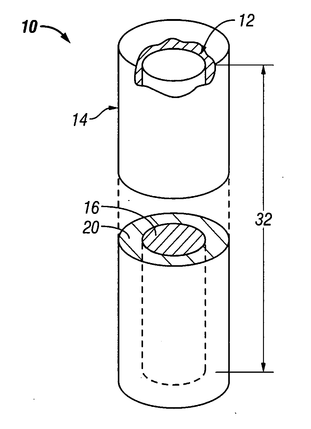
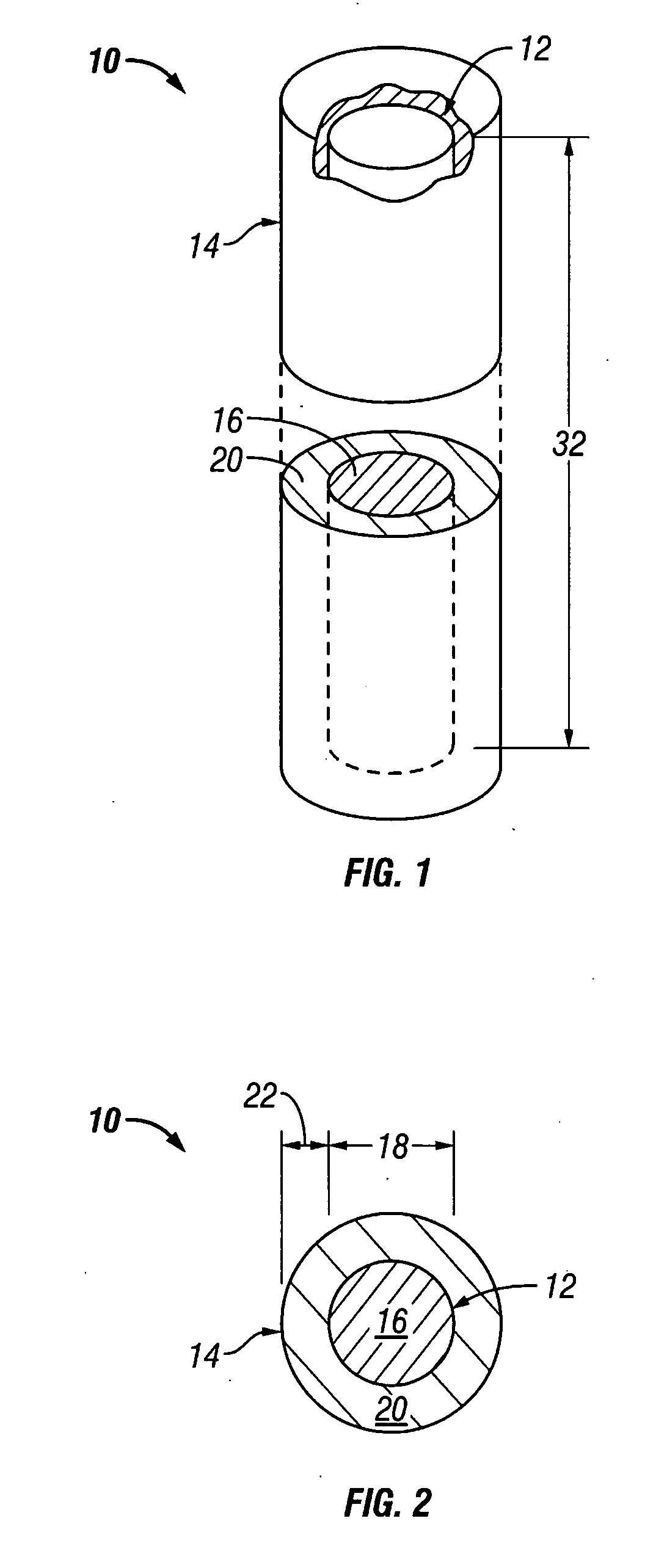
[0016] A nuclear fuel element according to the teachings provided herein may include a core comprising a high density solid solution fissile material that is substantially free of carbon and void space. A cladding substantially surrounds the core.
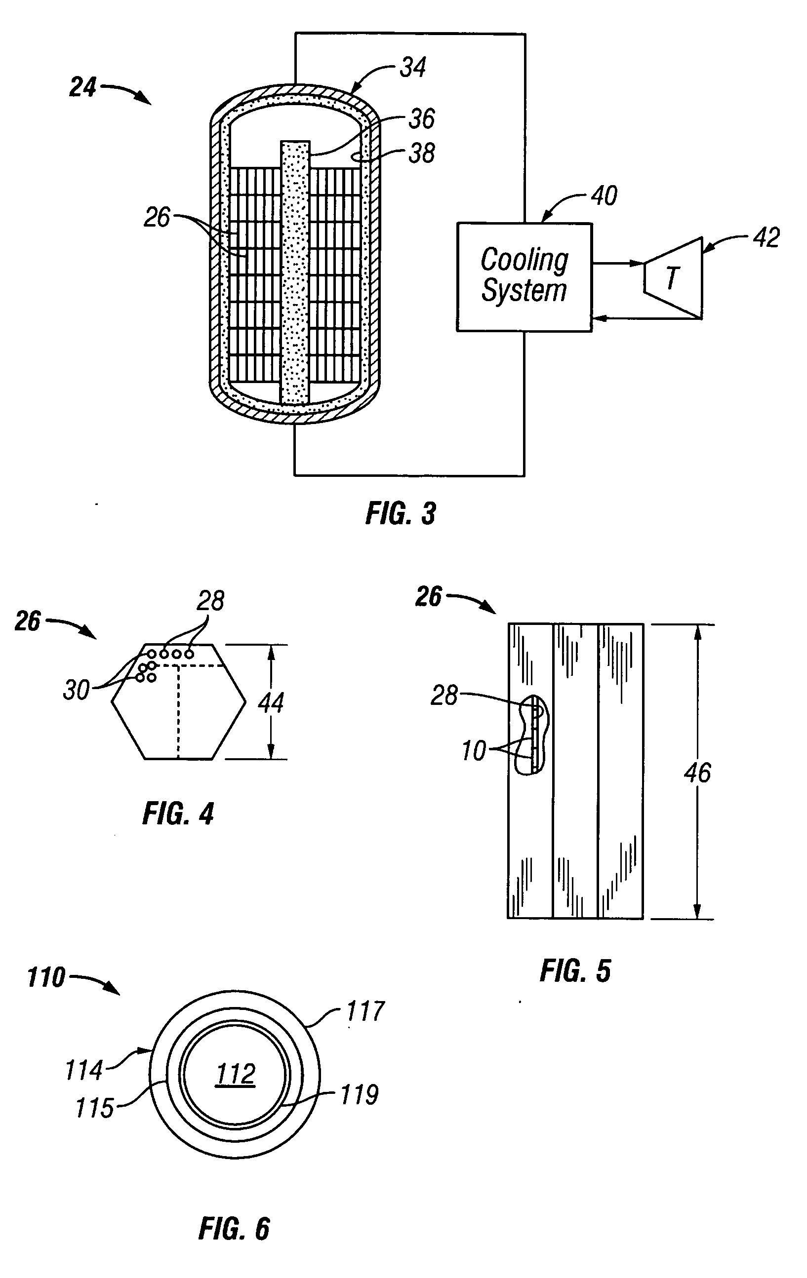
[0017] Also disclosed is a nuclear reactor system that may comprise a prismatic fuel block that

Problems solved by technology

Third, and currently unmatched by any other commercial nuclear power reactor in the world, the VHTR core design possesses inherent nuclear safety.
Although the VHTR core design possesses inherent safety and slow transient response behavior, the TRISO-coated fuel particles actually limit the total core power.
In addition to the narrow thermal safety margin mentioned previously, the use of TRISO-coated particle fuel has an additional drawback relative to the prismatic block VHTR core designs.
Unfortunately, the current particle packing fraction in the fuel compacts is practically limited to less than approximately 35%.
It should be noted that the relatively large fuel rod or compact diameters severely decrease the overall total core reactivity.
First, the larger fuel rod diameter displaces prismatic high density graphite (1.74 g / cc) with fuel compact materials, thereby displacing and hence reducing both the overall block carbon-to-uranium ratio (C:U).
Reduction of carbon in the block inhibits the neutron moderation and thermalization of fission neutrons resulting in a loss of reactivity.
Second, the relatively large diameter fuel rods reduce the U-238 self-shielding effect.
The small design window allowed by the packing fraction (<35%), enrichment (<20 wt %), and rod diameter limitations by no means allows for an optimized reactor design.

Method used


Image

  • High-density, solid solution nuclear fuel and fuel block utilizing same
  • High-density, solid solution nuclear fuel and fuel block utilizing same
  • High-density, solid solution nuclear fuel and fuel block utilizing same

Examples


example 1

[0053] The first burn-up calculation was for the initial VHTR core (554 g U-235 per block 26). For the TRISO-coated particle fuel case, the enrichment was 10.0 wt % U-235 with a particle packing fraction of 0.24715, UCO kernel size of 425 microns in diameter, UCO density of 10.50 g / cc, and a fuel rod diameter of 12.45 mm. For the UO2 fuel core 12 of the present invention, the enrichment was only 5.0 wt % with a diameter 18 of 3.06 mm. As mentioned, the core 12 was substantially encapsulated with a silicon carbide cladding 14 having a thickness 22 of about 1.5 mm. Thus, the overall diameter of the fuel element 10 was about 6.06 mm. The TRISO-coated particle fuel core goes subcritical at approximately 560 EFPD (Effective Full Power Day at 600 MWth total core power) and the core utilizing the fuel element 10 of the present invention at 630 EFPD. Use of the fuel element 10 of the present invention achieves a substantial increase of 70 EFPDs (13% increase). The important point here is th...

example 2

[0054] The second burn-up calculation was for a uniform core loading of reload blocks (776 g U-235 per block 26). In actual practice, only half of the core 34 would be reloaded in order to meet the 18-month power cycle goal. However for calculation purposes and one-to-one burn-up comparison the entire core 34 (i.e., 1020 fuel blocks 26) contained the 776 g U-235 loading. For the TRISO-coated particle fuel case, the enrichment was 14.0 wt % U-235 with a particle packing fraction of 0.24715, UCO kernel size of 425 microns in diameter, UCO density of 10.50 g / cc, and a fuel rod diameter of 12.45 mm. For the fuel core 12 (comprising UO2) of the present invention, the enrichment was again only 5.0 wt % with a core diameter 18 of 3.63 mm. Thus, including a cladding 14 having a thickness 22 of about 1.5 mm, the overall diameter of the fuel element 10 was about 6.63 mm. The reactor core with TRISO-coated particle fuel goes subcritical after approximately 890 EFPDs (Effective Full Power Day a...

example 3

[0055] The third burn-up calculation is essentially identical to the second burn-up calculation, except the enrichment of the UO2 fuel element 10 of the present invention is now increased slightly from 5.0 to 6.0 wt % and the diameter 18 of core 12 (e.g., comprising UO2) was diameter decreased slightly from 3.63 mm to 3.31 mm in order maintain the 776 g U-235 loading per fuel block 26. The increased enrichment is an attempt to extend the EFPD burn-up to better match the calculated TRISO-coated particle fuel core burn-up. As before, the TRISO-coated particle fuel core goes subcritical after approximately 890 EFPDs and the reactor core utilizing the fuel element 10 of the present invention now after 915 EFPD. For a one percent increase in the UO2 core enrichment, the burn-up is increased by 100 EFPDs and is now longer than the TRISO-coated particle fuel core by 25 EFPDs.

[0056] It is quite apparent that reactor cores utilizing the fuel elements described herein are superior to the TRI...


PUM


Abstract

A nuclear fuel element includes a core formed from a high density solid solution fissile material that is substantially free of carbon and void space. A cladding substantially surrounds the core.

Description

CONTRACTUAL ORIGIN OF THE INVENTION [0001] This invention was made with Government support under Contract DE-AC07-05ID14517 awarded by the U.S. Department of Energy. The Government has certain rights in the invention.TECHNICAL FIELD [0002] This invention relates generally to nuclear power systems in general and more specifically to improved nuclear fuel elements and a reactor systems utilizing the same. BACKGROUND [0003] The international Generation IV nuclear reactor program is chartered with the design and development of a new class of commercial power reactors to meet the growing demand worldwide for electricity and the production of hydrogen gas. The new Generation IV reactor designs must be better than the current Generation II operating commercial power reactors, and better even than the Generation III plants which have yet to be deployed. This requires the Generation IV reactors to have superior reactor safety, economics, sustainability, and proliferation-resistance relative ...

Claims


Application Information

Patent Timeline
IPC IPC(8): G21C3/00
CPCG21C3/02G21C3/623G21C3/64Y02E30/38G21Y2004/10G21Y2004/30G21Y2002/304Y02E30/30
Inventor STERBENTZ, JAMES W.
Owner MICRON TECH INC
Learn More