
System and method for therapy and diagnosis comprising optical components for distribution of radiation

Active Publication Date: 2007-03-15
SPECTRACURE
View PDF13 Cites 7 Cited by
  • Summary
  • Abstract
  • Description
  • Claims
  • Application Information

AI Technical Summary

Benefits of technology

[0015] The present invention overcomes the above identified deficiencies in the art and solves at least the above identified problems by providing a system and a method according to the appended patent claims, wherein a very practical and efficient implementation of interactive IPDT is achieved in that different optical measurements for diagnostics and dosimetry can be performed in an integrated and simple way by means of a system requiring minimal space. An important application of the invention is interactive, interstitial photodynamic therapy, and / or interactive photothermal tumour therapy.
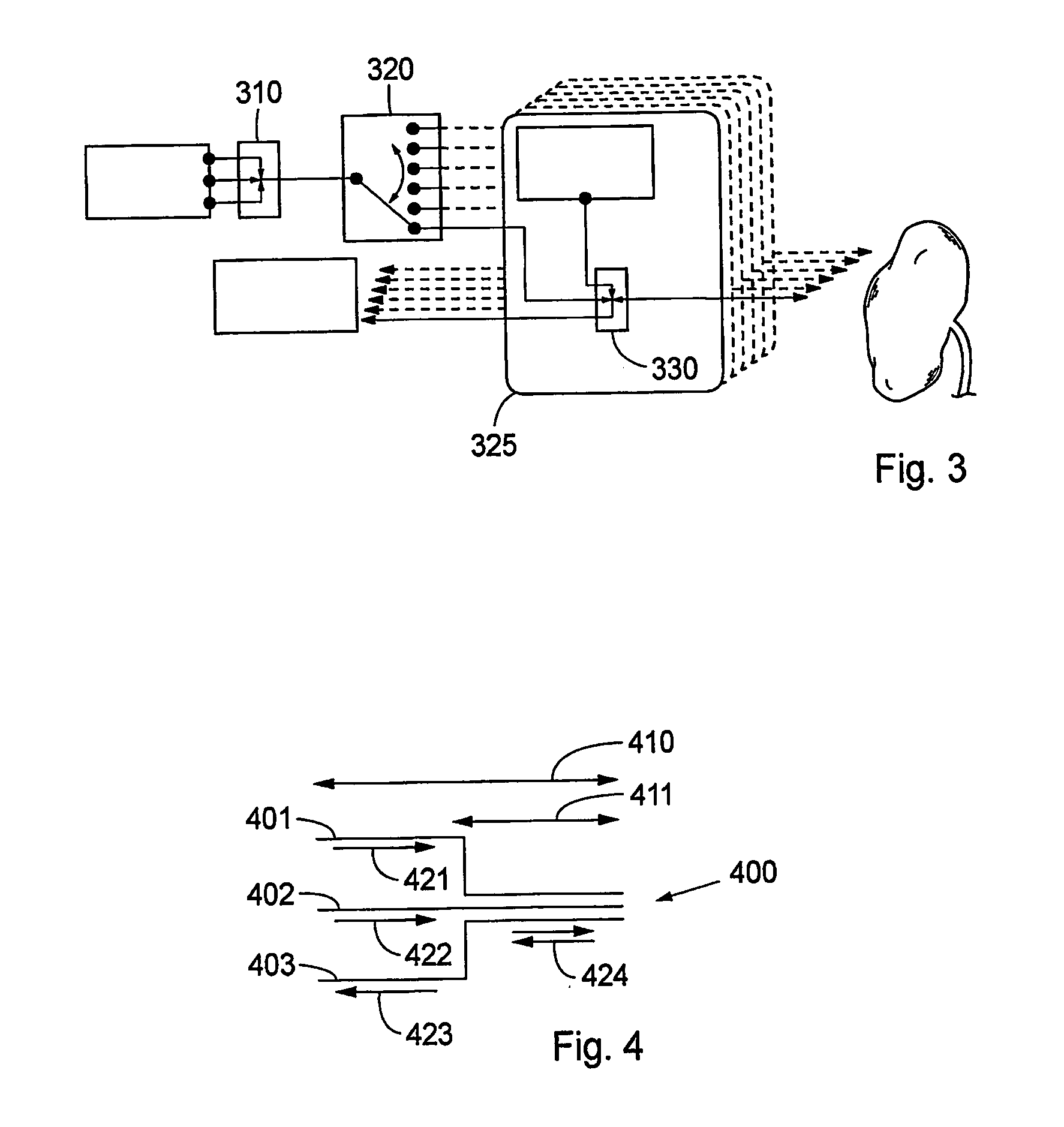
[0018] The use of non-mechanical switching elements based on optical principles offers several advantages over mechanical arrangements. Among others, these advantages comprise: high switching speed between different system operation modes (diagnosis, photodynamic therapy, thermal therapy); compactness and stability of the system; excellent optical parameters; long life of the system due to no mechanical wear of the components and due to many more switching cycles during a life-cycle of the elements of the system; and no switching noise, thus offering increased patient comfort.

Problems solved by technology

In spite of great progress within therapy, the tumour diseases continue to account for much human suffering, and are responsible for a high percentage of deaths in western countries.
Singlet oxygen is known to be particularly toxic to tissue; cells are eradicated and the tissue goes in necrosis.
The limited penetration in the tissue of the activating red radiation is a big drawback of PDT.
However, such open beam paths result in a strongly lossy beamsplitting and the resulting losses of light drastically impair the light distribution as well as the light measurement.
Furthermore, such a system must often be adjusted optically, which is also an important drawback in connection with clinical treatments.
The system is also large and heavy and difficult to integrate into a user-friendly apparatus.
However, only the use of a single wavelength light source is disclosed, it is thus not possible to have multiple diagnostics performed without manually exchanging the light source.
Moreover, it is not possible to switch between different constellations of the light fibres, i.e. all fibres always have the same function (light in or light out).
The device is not suitable for therapy.
Therefore, this device is not suited for interactive diagnosis and therapy.
Furthermore, there is no indication for a switch suitable for switching between different modes of diagnosis or therapy.
Furthermore, the disclosed device offers only substantially superficial diagnosis or treatment, interstitial tissue cannot be diagnosed or treated.
The device is also limited to existing body cavities and has the drawback that endoscopic probes are bulky and large compared to single optical fibres.
However, this system is not suited for diagnosis or treatment of tumours.
This device is also bulky compared to single fibres, similar to the above mentioned endoscope, bound to existing body cavities and works substantially superficial.
Furthermore it is not selective, i.e. all tissue aimed at is destroyed, independently if it is noxious or healthy.
However, although these mechanical constructions are improvements to the above described known IPDT system and although the above described problems are solved, these mechanical solutions have other limitations, related to e.g. mechanical inertia limiting the switching time between the different modes of a therapy and diagnosis system such as an interactive interstitial treatment system.

Method used


Image

  • System and method for therapy and diagnosis comprising optical components for distribution of radiation
  • System and method for therapy and diagnosis comprising optical components for distribution of radiation
  • System and method for therapy and diagnosis comprising optical components for distribution of radiation

Examples


Embodiment Construction

[0027] Different embodiments of the system according to the invention are now described with reference to the drawings. In order to simplify the description of the embodiments, reference numerals for similar elements shown in the drawings are not repeated throughout all the figures.

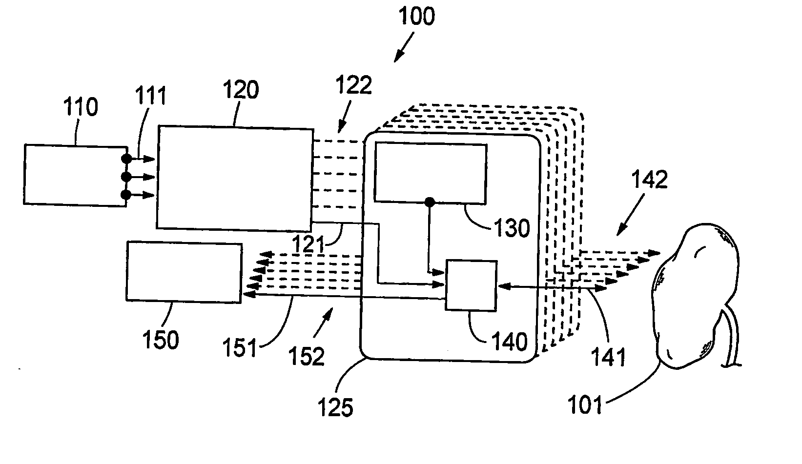
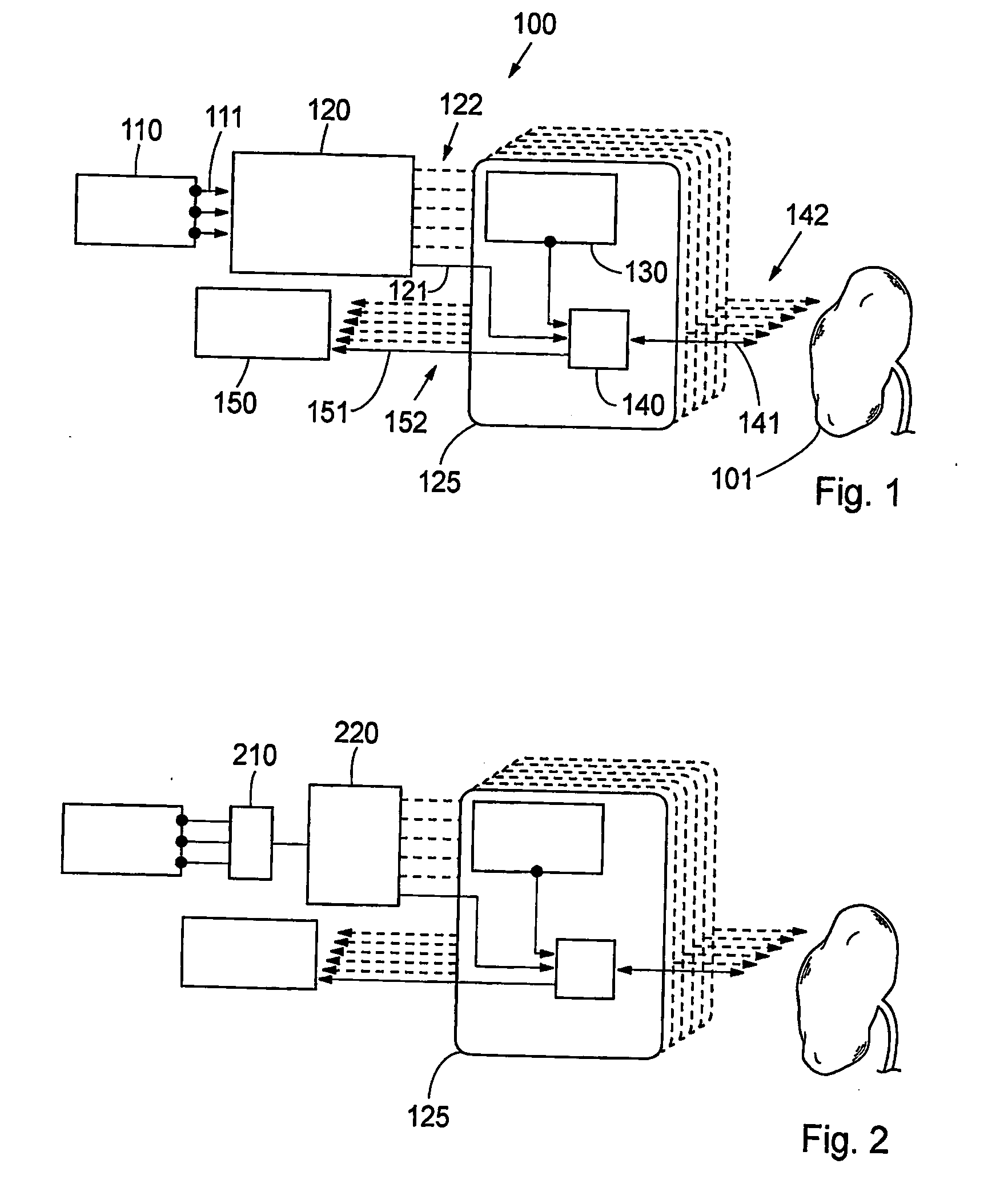
[0028] A general description of a system 100 according to a first embodiment of the invention is given with reference to FIG. 1. Accordingly, a system 100 for interactive IPDT comprises at least one diagnostic radiation source 110. The diagnostic radiation source 110 generates a diagnostic radiation. The optical radiation from at least one diagnostic optical radiation source 110 enters a diagnostic optical radiation coupling module 120. The optical radiation is preferably transmitted by means of optical radiation conductors 111. In general, the radiation conductors, described in this description of embodiments, are light guides such as optical fibres. The diagnostic radiation coupling module 120 distribu...


PUM


Abstract

A system and method for interactive therapy and diagnosis of a human or animal comprising at least one first radiation source for emission of a diagnostic radiation, at least one second radiation source for emission of a therapeutic radiation, and at least one radiation conductor adapted to conduct radiation to a tumour site at or in said human or animal. A non-mechanical operation mode selector directs the therapeutic radiation and / or the diagnostic radiation to the tumour site through the radiation conductors. The operation mode selector means is preferably a non-mechanical optical switch and / or an optical combiner. The system may be used for interactive interstitial photodynamic tumour therapy.

Description

FIELD OF THE INVENTION [0001] The invention relates generally to a system and a method for therapy and diagnosis in a subject. More particularly, the system and method relate to a system and method for tumour therapy and diagnosis in a human or animal subject. Even more particularly, the invention relates to a system and method for photodynamic therapy (PDT) and / or photothermal therapy (PTT) and / or photodynamic diagnosis (PDD) of a site on and / or in a human or animal body, wherein electromagnetic non-ionising radiation is conducted to the site for reaction with the radiation, wherein the system comprises an operation mode selector for distribution of radiation from at least one source of radiation to a reaction site, and / or from the reaction site to at least one radiation sensor, respectively, and wherein the reaction site generally is a tumour site with a tumour, such as a malignant tumour. BACKGROUND OF THE INVENTION [0002] Within the field of medical therapy of tumour diseases, a...

Claims


Application Information

Patent Timeline
IPC IPC(8): A61B5/00A61N1/39A61BA61B17/00A61B18/20A61N5/06
CPCA61B5/0071A61B5/0084A61B2017/00057A61N2005/0629A61N5/0601A61N5/062A61N2005/0612A61B2018/208A61N2005/063A61N2005/0659A61N2005/0661A61N2005/0662A61N2005/0663A61N5/067
Inventor THOMPSON, MARCELO SOTOENGELS, STEFAN ANDERSSONSVANBERG, SUNE
Owner SPECTRACURE
Learn More