
Apparatus for and method of determining quadrature code timing from pulse-shape measurements made using an in-phase code

a quadrature code and pulse-shape technology, applied in the field of systems for measuring the pulse shape of broadcast spreadspectrum signals, can solve the problems of gps receivers not being able to directly acquire and track p-codes, adversely affecting code synchronization operations, and affecting the accuracy of the received signal, so as to eliminate associated biases

Active Publication Date: 2007-03-15
NOVATEL INC
View PDF36 Cites 45 Cited by
  • Summary
  • Abstract
  • Description
  • Claims
  • Application Information

AI Technical Summary

Benefits of technology

[0019] The invention is a pre-correlation filter and a receiver that utilizes the filter to determine the precise timing of, for example, a PRN code on the quadrature channel of a received signal using an image of the average chip shape that the filter forms for a PRN code on the in-phase channel. The image is expressed as a time series of complex power measurements along the length of a single chip. The averaging process retains the detail of the composite in-phase signal (direct plus multipath signals) while reducing the level of signal noise by an amount proportional to the length of the averaging process. An analysis of the image reveals that there is, in the in-phase channel signal that is averaged, information from the quadrature channel signal. The quadrature channel signal information produces, in the image of the average chip shape of the in-phase channel PRN code, a “wiggle” that corresponds to the timing of the chips of the quadrature channel PRN code. The receiver can thus detect the chip edges of the quadrature PRN code directly from an analysis of the high frequency phase modulations of the complex vector of samples that represents the average chip shape. Specifically, using GPS signals, the receiver detects the P-code transitions by synchronizing to the 10.23 MHz phase modulations in the complex vector of samples that represent the averaged chip shape. The receiver uses the detected P-code transitions and, more particularly, the P-code transitions that are closest to the C / A code transitions, to produce P-code phase information that is used in pseudorange calculations to remove biases associated with timing differences between the transmission of the in-phase and quadrature PRN codes. The calculated pseudoranges for the in-phase PRN code, in the example the C / A code, then have the same accuracy as the pseudoranges generated using full P-code chip tracking or semi-codeless P-code tracking techniques, without requiring the use of local P-code generators and the associated P-code tracking hardware.
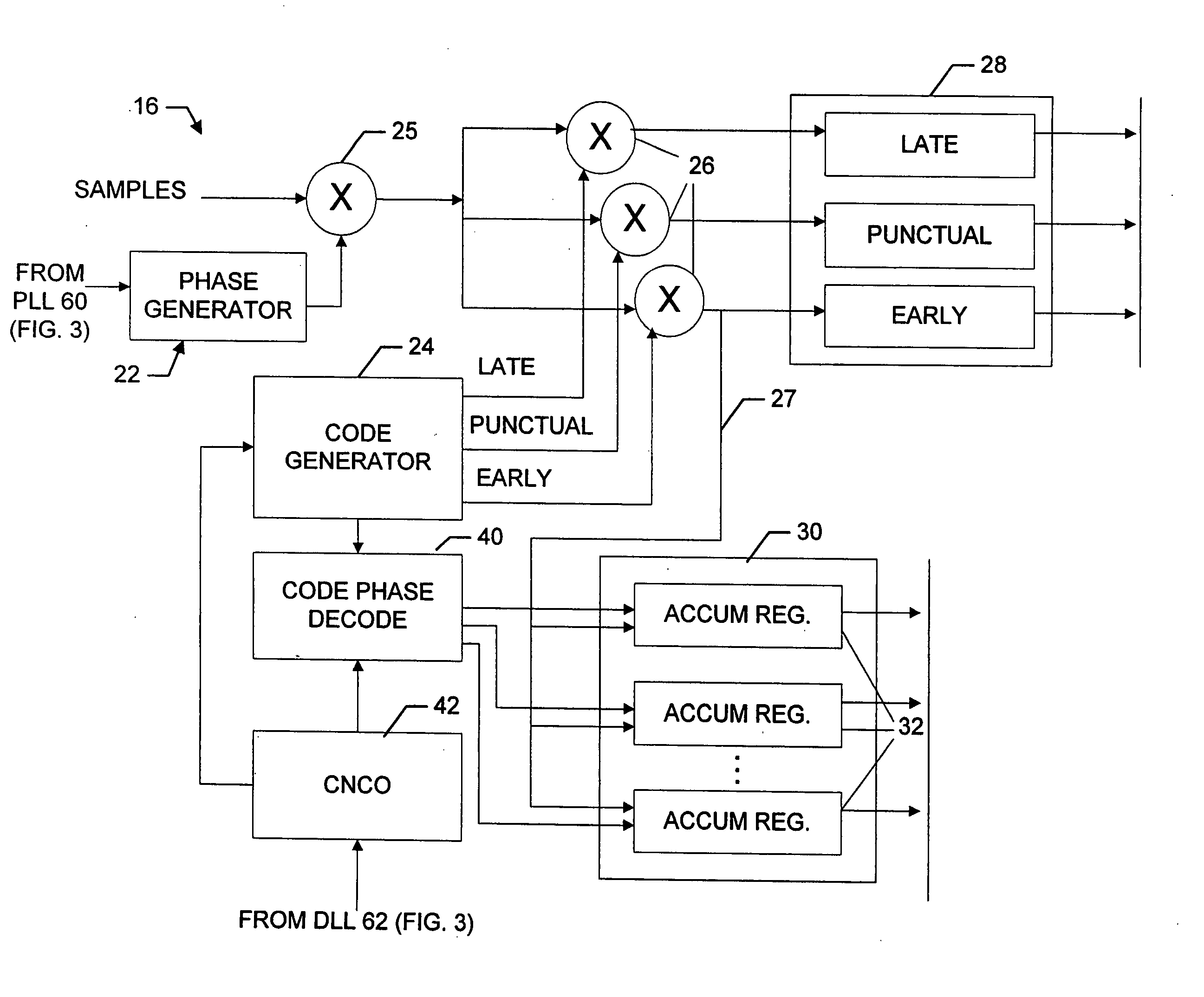
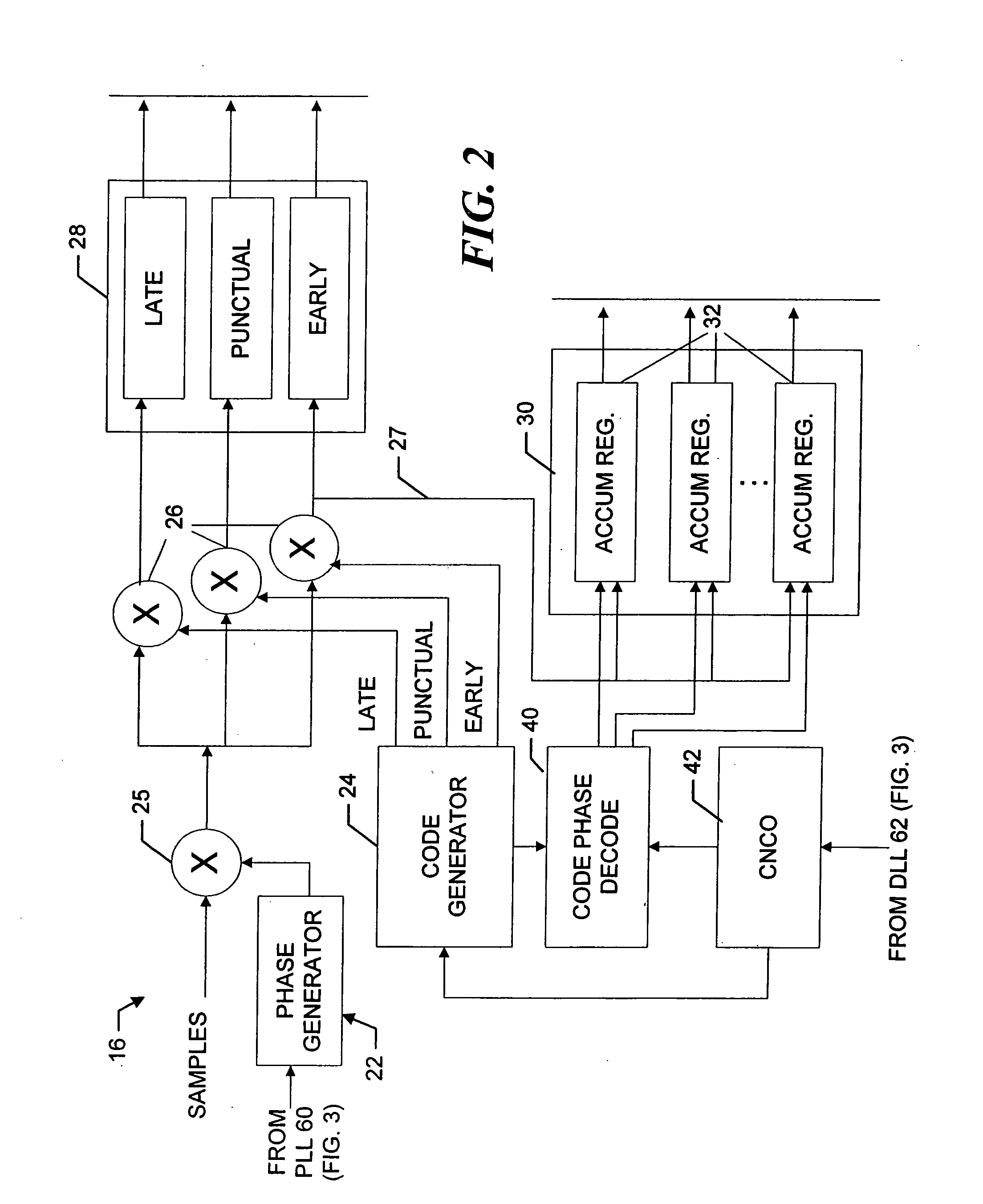
[0021] The length of the chip is divided into a plurality of “ranges,” that is, into fractions of a chip. The ranges may but need not be the same size across the chip, and preferably the ranges are smaller near the rising edge of the chip. The ranges are associated with the respective complex accumulation registers. When a sample is taken, a corresponding measurement is added to the appropriate I and Q accumulation registers that are associated with the range that includes the code phase angle estimated for the sample. As discussed in more detail below, the complex accumulation registers act as a pre-correlation filter, by collecting the measurements at sample times that are asynchronous with the code rate. In this way, the system avoids including associated correlation errors in the filtering process.
[0022] The system accumulates the measurements over many chips. The accumulation has essentially the same effect as a low-pass filter, and thus, wide-bandwidth noise is suppressed. The accumulated measurements, which provide the average chip shape of at least the direct path signals, are used by a multipath mitigation processing technique to compute the error of the code tracking loop due to multipath interference. The computed multipath error is then used to correct the in-phase channel code tracking loop, and thereby, provide more accurate pseudorange measurements. The multipath mitigation processing may also be used to compute the error of the in-phase channel carrier tracking loop due to multipath interference, with the computed error being used to correct the carrier tracking loop to provide even greater accuracy.
[0025] The receiver also detects quadrature channel PRN code transitions from the demodulated in-phase PRN code signal strength. The receiver uses information from the accumulated measurements to determine the location of the quadrature PRN code transitions that are closest to the chip transitions in the in-phase PRN code. As described below, the receiver may use the same or a separate array of registers to accumulate the measurements associated with the detected quadrature PRN code transitions. Based on the relative timing of the associated transitions in the in-phase PRN code and the quadrature PRN code, the receiver can eliminate associated biases from the in-phase code pseudorange measurements without having to acquire and track the quadrature PRN code. Accordingly, the receiver need not include a local generator for the quadrature PRN code and / or associated P-code tracking hardware.

Problems solved by technology

This distortion of the received signal adversely affects code synchronization operations because the correlation measurements, which measure the correlation between the local PRN code and the received signal, are based on the entire received signal—including the multipath components thereof.
The distortion may be such that the receiver attempts to synchronize to a multipath signal instead of to the direct-path signal.
Over a relatively long period of time, (a few seconds) the multipath interference affects every chip of the incoming signal the same way.
GPS receivers can not directly acquire and track the P-code.
This adds complexity to the receivers and also increases the cost of the receivers.

Method used


Image

  • Apparatus for and method of determining quadrature code timing from pulse-shape measurements made using an in-phase code
  • Apparatus for and method of determining quadrature code timing from pulse-shape measurements made using an in-phase code
  • Apparatus for and method of determining quadrature code timing from pulse-shape measurements made using an in-phase code

Examples


Embodiment Construction

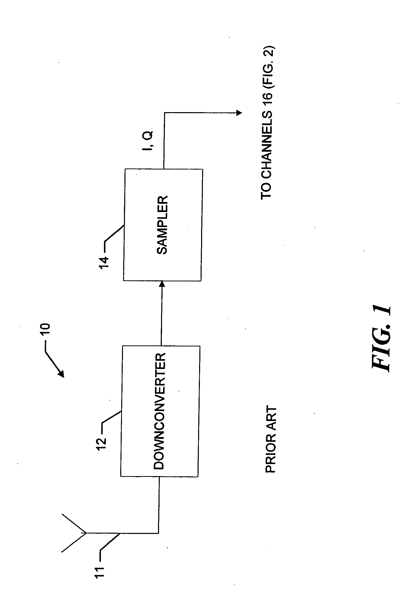
[0036] Referring to FIG. 1, a receiver 10 receives over an antenna 11 a composite signal that includes direct path signals and associated multipath signals. A downconverter 12 and sampler 14 operate in a conventional manner, to downconvert the received composite signal and in the exemplary embodiment take sequential samples of the downconverted signal. The sequential samples are provided to the respective channels 16 (FIG. 2).

[0037] Referring now to FIG. 2, a given channel 16 which in the example demodulates an in-phase PRN code, that is, a PRN code that is transmitted on the in-phase channel of the satellite signal, includes a mixer 25 that removes the carrier from the samples by mixing them with an estimate of the associated carrier phase. Thus, in a known manner, the sequential samples are each mixed with both sine and cosine transformations of the estimated carrier phase to produce a corresponding complex I and Q sample pair. The carrier phase estimate is generated by a phase g...


PUM


Abstract

A receiver employs a pre-correlation filter to determine the precise timing of, for example, a PRN code on the quadrature channel of a received signal, using an image of the average chip shape that the filter forms for a PRN code on the in-phase channel. The image is expressed as a time series of complex power measurements along the length of a single chip. The averaging process retains the detail of the composite in-phase signal (direct plus multipath signals) while reducing the level of signal noise by an amount proportional to the length of the averaging process. An analysis of the image reveals that there is, in the in-phase channel signal that is averaged, information from the quadrature channel signal. The quadrature channel signal information produces, in the image of the average chip shape of the in-phase channel PRN code, a “wiggle” that corresponds to the timing of the chips of the quadrature channel PRN code. The receiver detects the chip edges of the quadrature PRN code directly from an analysis of the high frequency phase modulations of the complex vector of samples that represents the average chip shape. Using GPS signals, the receiver detects the P-code transitions by synchronizing to the 10.23 MHz phase modulations in the complex vector of samples that represent the averaged chip shape. The receiver uses the detected P-code transitions and, more particularly, the P-code transitions that are closest to the C / A code transitions, to produce P-code phase information that the receiver uses pseudorange calculations to remove biases associated with timing differences between the transmission of the in-phase and quadrature PRN codes.

Description

CROSS-REFERENCE TO RELATED APPLICATIONS [0001] The present application is related to U.S. patent application Ser. No. 10 / 823,030, which was filed on Apr. 13, 2004, by Patrick C. Fenton for a APPARATUS FOR AND METHOD OF MAKING PULSE-SHAPE MEASUREMENTS and is hereby incorporated by reference.BACKGROUND OF THE INVENTION [0002] 1. Field of the Invention [0003] The invention relates generally to systems for measuring the pulse shape of a broadcast spread-spectrum signal and, in particular, to systems that provide estimates of quadrature code chip times based on the pulse shape measurements of the code chips of an in-phase code. [0004] 2. Background Information [0005] One example of a system that utilizes broadcast spread-spectrum signals is a global positioning system, such as, GPS, GLONAS or Galileo systems. The system receivers determine their global positions based on the signals they receive from associated satellites. The broadcast spread-spectrum signal generally consists of in-pha...

Claims


Application Information

Patent Timeline
IPC IPC(8): H04B1/00
CPCG01S19/30H04B2201/70715H04B1/7075
Inventor FENTON, PATRICK C.
Owner NOVATEL INC
Learn More