
Methods and apparatus for varying a supply voltage or reference voltage using independent control of diode voltage in asymmetrical double-gate devices

a diode voltage and independent control technology, applied in the direction of information storage, static storage, digital storage, etc., can solve the problems of limiting the viable operating frequency and the diminishing of the modulation effect, and achieve the effect of improving the power and performance of the processing uni

Inactive Publication Date: 2007-03-01
IBM CORP
View PDF16 Cites 43 Cited by
  • Summary
  • Abstract
  • Description
  • Claims
  • Application Information

AI Technical Summary

Benefits of technology

The present invention provides methods and apparatus for controlling the supply voltage and reference voltage in an integrated circuit. This is achieved by using an independently controlled asymmetrical double-gate device that can adjust the threshold voltage, VT, through a back-gate bias. The invention also provides multiple voltage islands with different voltage levels, each containing an independently controlled asymmetrical double-gate device for power control and a processing unit with an oscillator, at least one independently controlled asymmetrical double-gate device, a phase detector, and a charge pump for adjusting the back-gate bias based on the comparison. The invention can improve power and performance of the processing unit and provide greater flexibility in voltage adjustments.

Problems solved by technology

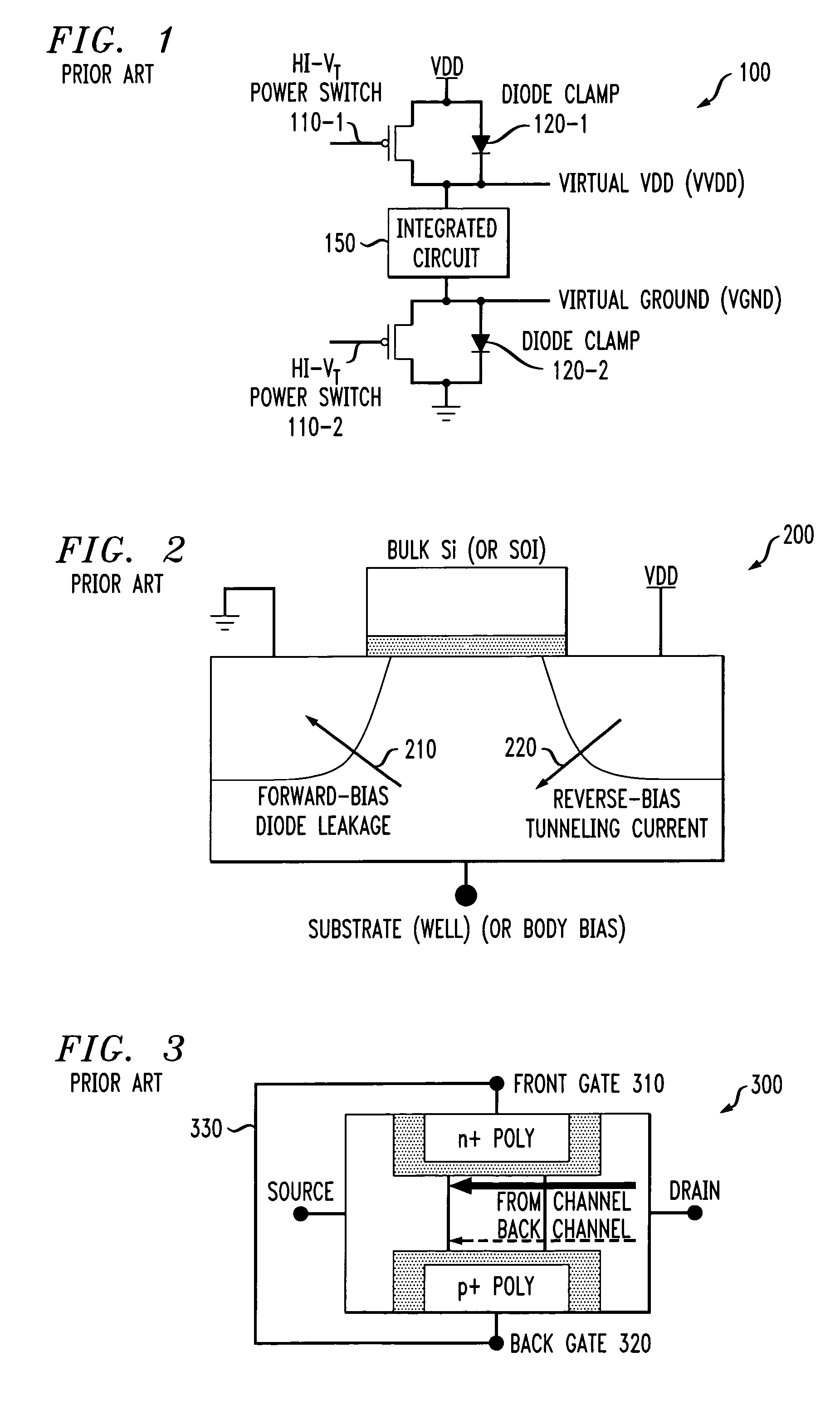
Furthermore, it is known that the VT modulation effect diminishes with device scaling due to a low body factor in the scaled, low VT transistor.
Finally, the distributed RC for the well / body contact limits the viable operating frequency.
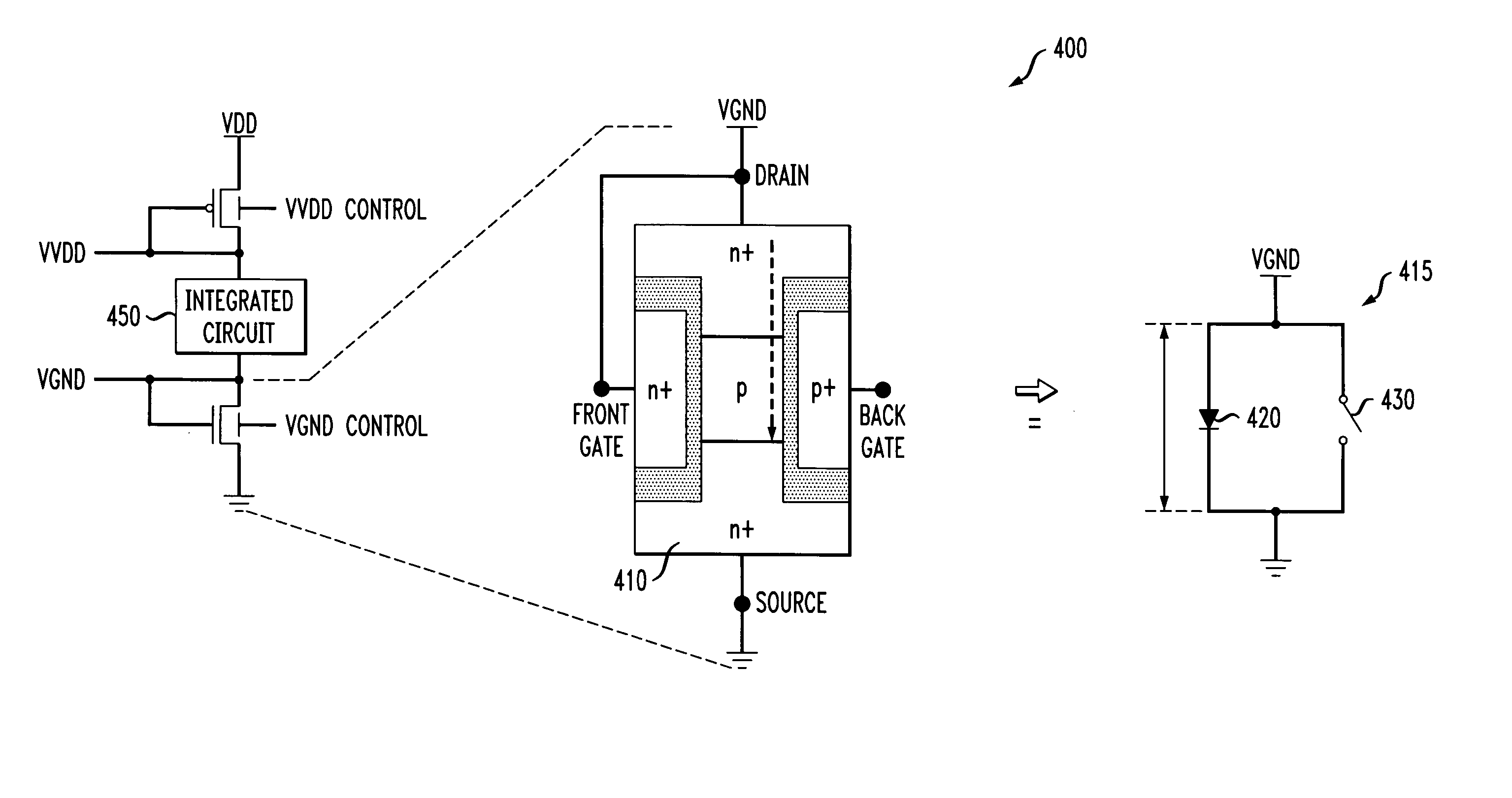
Thus, the disclosed asymmetrical double-gate devices cannot be used to provide a variable VT diode and thereby control the virtual VDD or virtual Ground in the integrated circuit 100 of FIG. 1.

Method used


Image

  • Methods and apparatus for varying a supply voltage or reference voltage using independent control of diode voltage in asymmetrical double-gate devices
  • Methods and apparatus for varying a supply voltage or reference voltage using independent control of diode voltage in asymmetrical double-gate devices
  • Methods and apparatus for varying a supply voltage or reference voltage using independent control of diode voltage in asymmetrical double-gate devices

Examples


Embodiment Construction

[0020] The present invention provides techniques for varying a supply voltage or a reference voltage using one or more independently controlled asymmetrical double-gate devices. The present invention recognizes that the front-channel VT (and current) of the asymmetrical double-gate devices can be modulated using independent control, such as back-gate biasing, through gate-to-gate coupling. This VT modulation mechanism is significantly stronger than the existing well / body bias in bulk CMOS and PD / SOI devices, as discussed above in conjunction with FIG. 2. Furthermore, the effect improves with device scaling due to stronger gate-to-gate coupling in thinner film or thinner gate oxides (or both), and the frequency is only limited by the gate RC, in the same manner as core logic.

[0021] According to one aspect of the invention, a variable threshold voltage, VT, is provided using independently controlled asymmetrical double-gate devices. FIG. 4 is a circuit diagram of a CMOS circuit 400 i...


PUM


Abstract

Methods and apparatus are provided for varying one or more of a supply voltage and reference voltage in an integrated circuit, using independent control of a diode voltage in an asymmetrical double-gate device. An integrated circuit is provided that is controlled by one or more of a supply voltage and a reference voltage. The integrated circuit comprises an independently controlled asymmetrical double-gate device to adjust one or more of the supply voltage and the reference voltage. The independent control may comprise, for example, a back gate bias. The independently controlled asymmetrical double-gate device may be employed in a number of applications, including voltage islands, static RAM, and to improve the power and performance of a processing unit.

Description

STATEMENT OF GOVERNMENT RIGHTS [0001] This invention was made with Government support under Contract No. NBCH3039004 awarded by Defense Advanced Research Projects Agency (DARPA). The Government has certain rights in this invention.FIELD OF THE INVENTION [0002] The present invention relates generally to techniques for varying a voltage by a diode voltage in various integrated circuits and, more particularly, to techniques for providing a variable diode voltage using independently controlled asymmetrical double-gate devices. BACKGROUND OF THE INVENTION [0003] A number of techniques have been proposed or suggested for containing power / leakage, improving performance, and extending scaling, including voltage islands, dynamic VDD, and separate supplies for logic and SRAM. For example, one commonly used technique drops the supply voltage (or raises the Ground voltage) through a metal oxide semiconductor (MOS) diode by one threshold voltage, VT. MOS diodes are also widely used in power-gati...

Claims


Application Information

Patent Timeline
Patent Type & Authority Applications(United States)
IPC IPC(8): G11C5/14
CPCG11C11/417G11C5/147G11C11/412
Inventor CHUANG, CHING-TE KENTKIM, KEUNWOOKUANG, JENTE BENEDICTNGO, HUNG CAINOWKA, KEVIN JOHN
Owner IBM CORP
Learn More