Duplexer and ladder type filter
- Summary
- Abstract
- Description
- Claims
- Application Information
AI Technical Summary
Benefits of technology
Problems solved by technology
Method used
Image
Examples
first exemplary embodiment
(First Exemplary Embodiment)
[0108] A first exemplary embodiment of the present invention is an example of a duplexer having the transmit bandwidth of 1920 MHz to 1980 MHz and the receive bandwidth of 2110 MHz to 2170 MHz. FIG. 8A shows a circuit configuration of the duplexer in accordance with the first exemplary embodiment of the present invention. In this duplexer, a transmit filter 10 (first filter) is connected between an antenna terminal Ant and a transmitting terminal Tx. Similarly, a receive filter 20 (second filter) is connected between the antenna terminal Ant and the receiving terminal Rx.
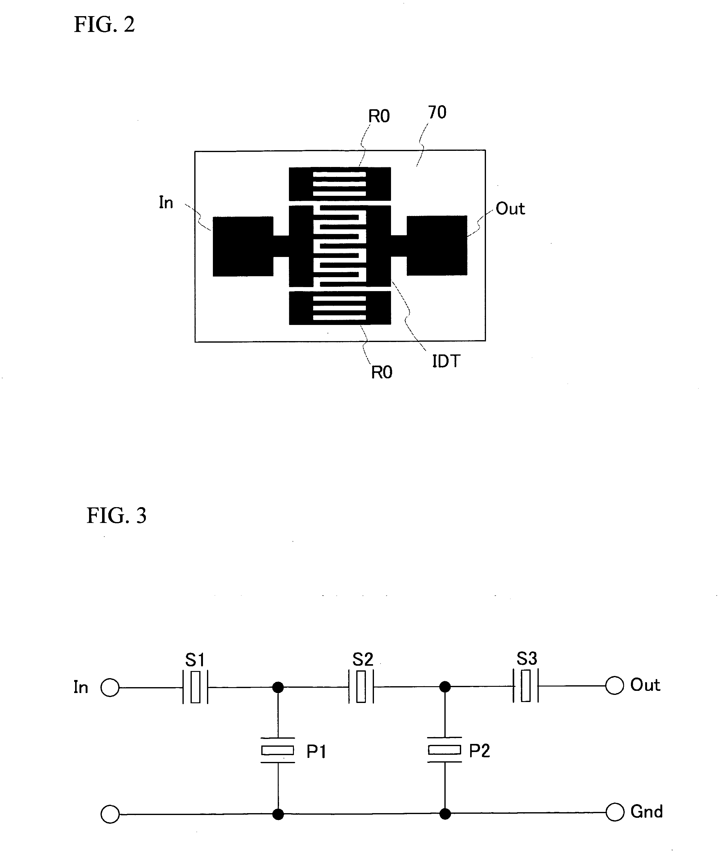
[0109]FIG. 9 shows a circuit configuration of the transmit filter 10. Referring to FIG. 9, the transmit filter 10 is a ladder type filter that includes multiple series resonators S1 through S4 and parallel resonators P1 and P2. In addition, an inductor L1 is connected in parallel with the series resonator S1 arranged closest to the antenna terminal Ant. Further, an inductor LP1 is connec...
second exemplary embodiment
(Second Exemplary Embodiment)
[0118] A second exemplary embodiment is an example in which the capacitance value of the series resonator arranged closest to the antenna terminal Ant is set smaller than those of other series resonators in the transmit filter 10 and in the receive filter 20, in order to improve the insertion loss more than that obtained in the first exemplary embodiment. In the duplexer having the same configuration as that of the duplexer employed in the first exemplary embodiment, desirable relationship of the series resonators has been studied.
[0119] Firstly, a description will now be given of the definition of the capacitance value of the series resonator in the ladder type filter. FIG. 12 shows a basic segment of the ladder type filter in which one series resonator S and one parallel resonator P are provided. FIG. 13A shows a ladder type filter F1, in which four basic segments of FIG. 12 are arranged between the antenna terminal Ant and the terminal Tx / Rx and conn...
third exemplary embodiment
(Third Exemplary Embodiment)
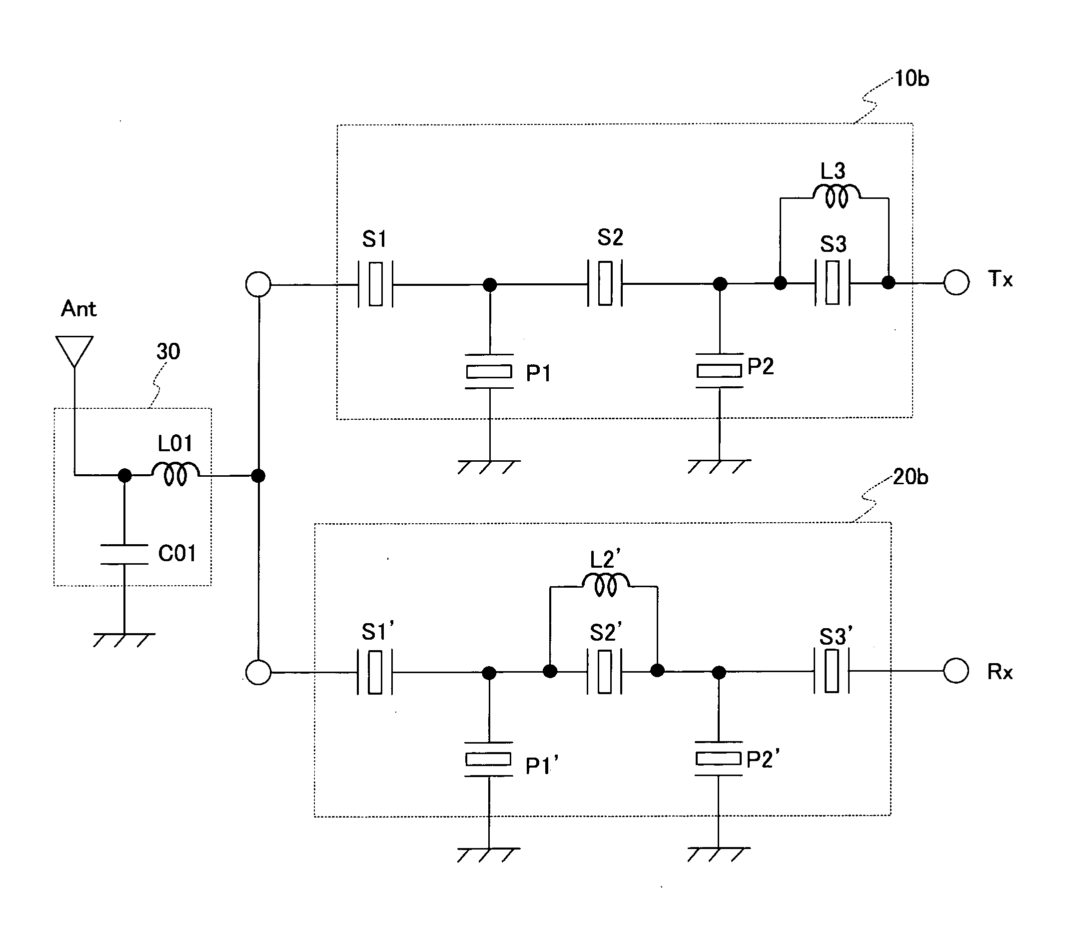
[0128]FIG. 18A shows a circuit configuration of the duplexer in accordance with a third exemplary embodiment of the present invention. The inductors are not connected to the series resonators S1 through S4 in a transmit filter 10a with respect to the duplexer employed in first exemplary embodiment of FIG. 8A. In addition, a matching circuit 30a is connected between the transmit filter 10a and the antenna terminal Ant. In the third exemplary embodiment, the same components and configurations as those of FIG. 8A have the same reference numerals and a detailed explanation will be omitted.
[0129]FIG. 18B shows a circuit configuration of a variation of the duplexer in accordance with the third exemplary embodiment of the present invention. The inductors are not connected to the series resonators S1′ through S4′ in a receive filter 20a with respect to the duplexer of FIG. 8A employed in first exemplary embodiment. In addition, a matching circuit 30b is connecte...
PUM
 Abstract
Description
Claims
Application Information
 - R&D
- Intellectual Property
- Life Sciences
- Materials
- Tech Scout
- Unparalleled Data Quality
- Higher Quality Content
- 60% Fewer Hallucinations
Browse by: Latest US Patents, China's latest patents, Technical Efficacy Thesaurus, Application Domain, Technology Topic, Popular Technical Reports.
© 2025 PatSnap. All rights reserved.Legal|Privacy policy|Modern Slavery Act Transparency Statement|Sitemap|About US| Contact US: help@patsnap.com


