
Electret and electret capacitor

Active Publication Date: 2007-02-08
PANASONIC CORP
View PDF29 Cites 27 Cited by
  • Summary
  • Abstract
  • Description
  • Claims
  • Application Information

AI Technical Summary

Benefits of technology

[0015] In accordance with the present invention, there can be provided an element to which an electret condenser has been applied and which has an electret structure excellent in moisture resistance, such as an ECM. By producing such an ECM by using a MEMS technology, it becomes possible to provide a small-size ECM which does not require a charge supply circuit. Thus, the present invention renders it possible to implement a high-reliability, small-size, and high-performance microphone. In addition, it also becomes possible to widely supply various practical devices each equipped with the microphone to a society.

Problems solved by technology

However, since these materials are inferior in thermal resistance, the problem has been encountered that they are difficult to use as elements for reflow when mounted on substrates.

Method used


Image

  • Electret and electret capacitor
  • Electret and electret capacitor
  • Electret and electret capacitor

Examples


embodiment

[0053] (Embodiment)

[0054] Referring to the drawings, an electret condenser according to an embodiment of the present invention will be described by using the case where it is applied to an ECM as an example.

[0055] A description will be given first to the ECM as an element to which the electret condenser according to the present embodiment has been applied.

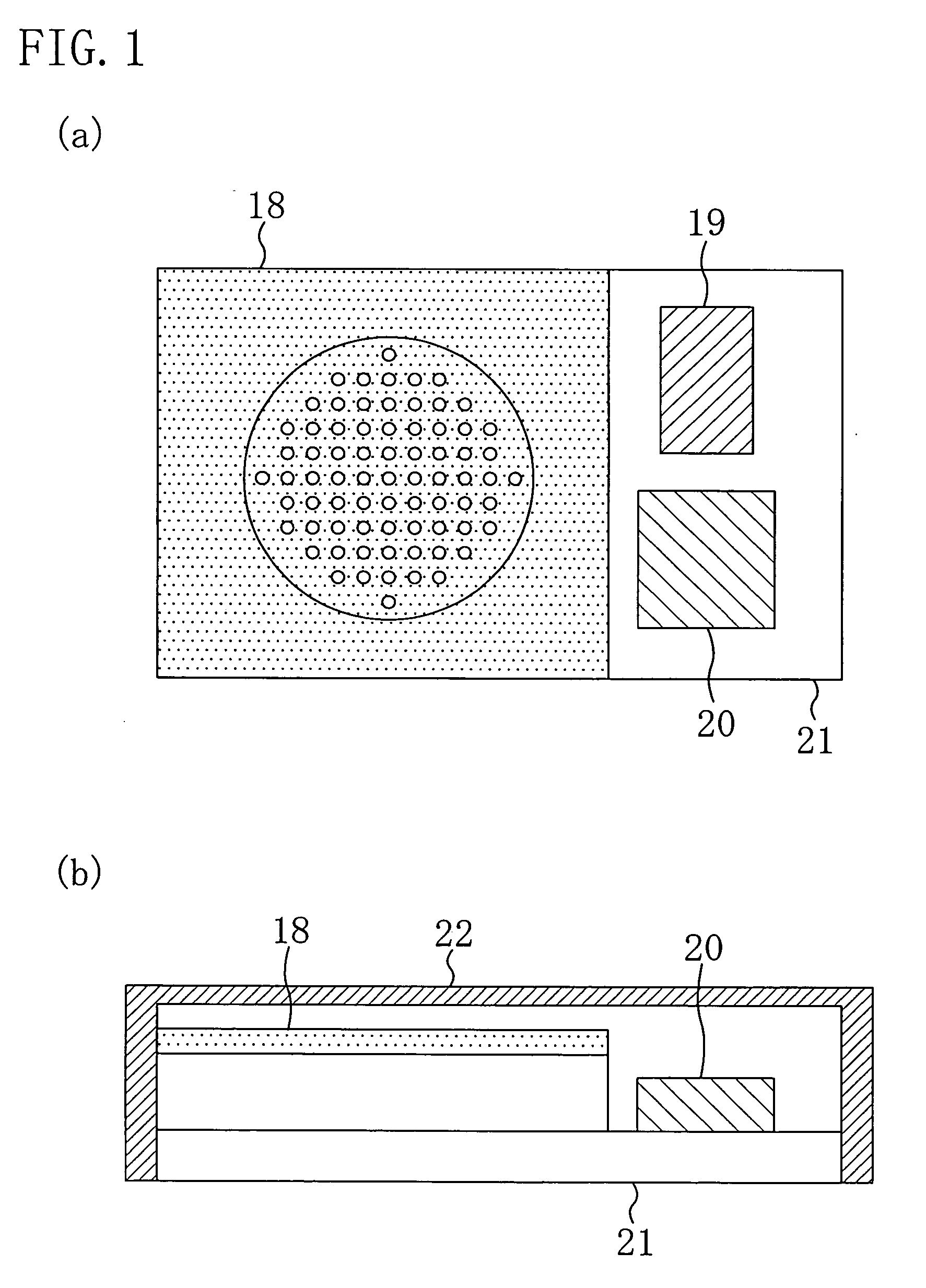
[0056] FIGS. 1(a) and 1(b) are structural views of the ECM according to the present embodiment, of which FIG. 1(a) is a plan view of the ECM and FIG. 1(b) is a cross-sectional view of the ECM.

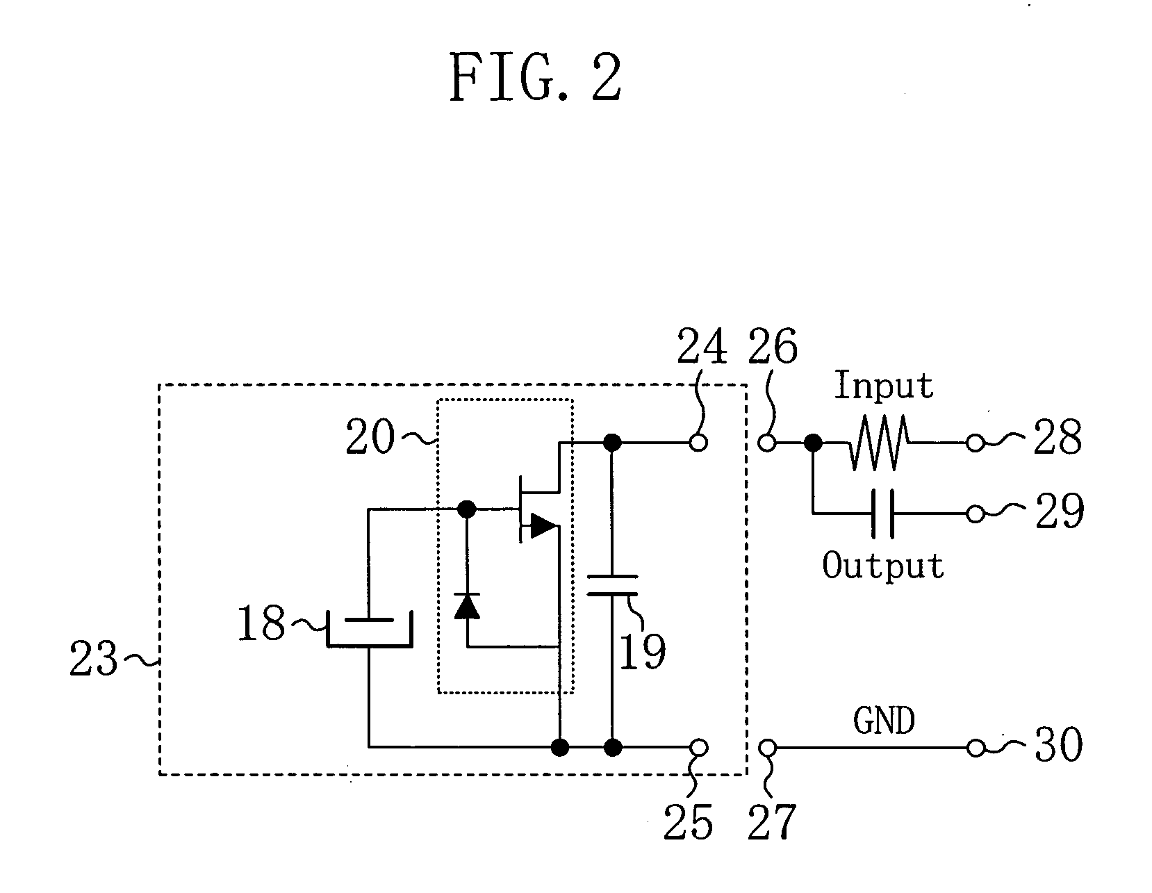
[0057] As shown in FIGS. 1(a) and 1(b), the ECM according to the present embodiment is comprised of: a microphone portion 18; a SMD (Surface Mounted Device) 19 such as a condenser; and a FET (Field Effect Transistor) portion 20 which are mounted on a printed board 21. As shown in FIG. 1(b), the printed board 21 with the microphone portion 18, the SMD 19, and the FET portion 20 mounted thereon is protected by a case 22, though the depiction ...


PUM


Abstract

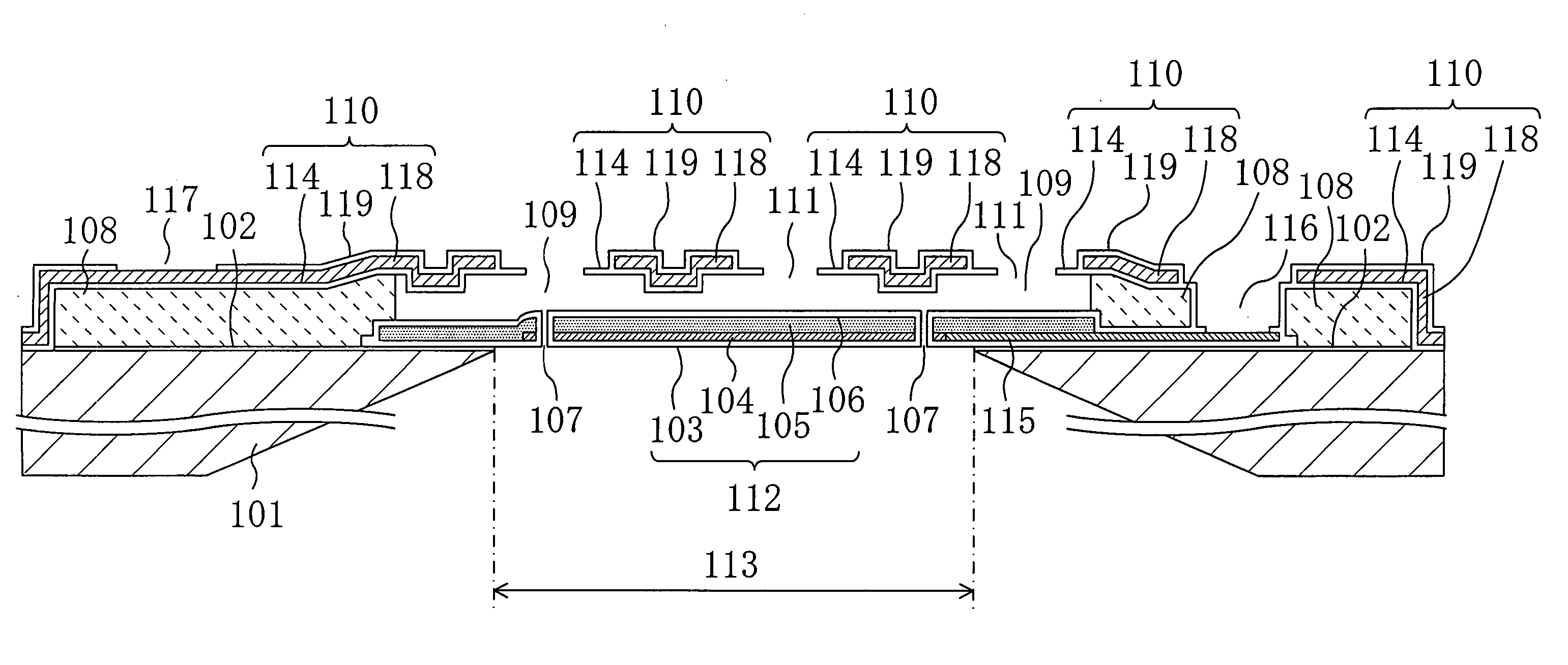
A silicon nitride film (103) and a silicon nitride film (106) are formed to cover a charged silicon oxide film (105) serving as an electret.

Description

TECHNICAL FIELD [0001] The present invention relates to an electret condenser having a vibrating electrode and a fixed electrode and, more particularly, to an electret condenser formed by using a MEMS (Micro Electro Mechanical Systems) technology. Background Art [0002] Organic high-molecular polymers such as FEP (Copolymer of Tetrafluoroethylene (TFE) and Hexafluoropropylene (HFP)) materials have been used conventionally for electret elements which are dielectric materials each having a permanent electric polarization and applied to devices such as a condenser microphone. However, since these materials are inferior in thermal resistance, the problem has been encountered that they are difficult to use as elements for reflow when mounted on substrates. [0003] As a solution to the problem, an electret using a silicon oxide film as shown in Patent Document 1, instead of an organic high-molecular polymer, has been proposed in recent years to provide a thinner-film and smaller-size electr...

Claims


Application Information

Patent Timeline
IPC IPC(8): H01L41/00H01G5/013H01G5/16H01G7/02H04R19/01
CPCH01G5/0136H01G5/16H04R2499/11H04R19/016H01G7/025H04R7/02H04R19/01
Inventor YAMAOKA, TOHRUOGURA, HIROSHIMIYOSHI, YUICHISASAKI, TOMOYUKI
Owner PANASONIC CORP
Learn More