
Electro-motive machine using halbach array

a technology of halbach array and electric motor, which is applied in the direction of dynamo-electric machines, magnetic circuit rotating parts, magnetic circuit shapes/forms/construction, etc., can solve the problems of limited utility of such devices, inability to meet the needs of current halbach array, and specific limitations of existing halbach array limitations

Inactive Publication Date: 2007-02-08
DUNN TOM +3
View PDF6 Cites 22 Cited by
  • Summary
  • Abstract
  • Description
  • Claims
  • Application Information

AI Technical Summary

Benefits of technology

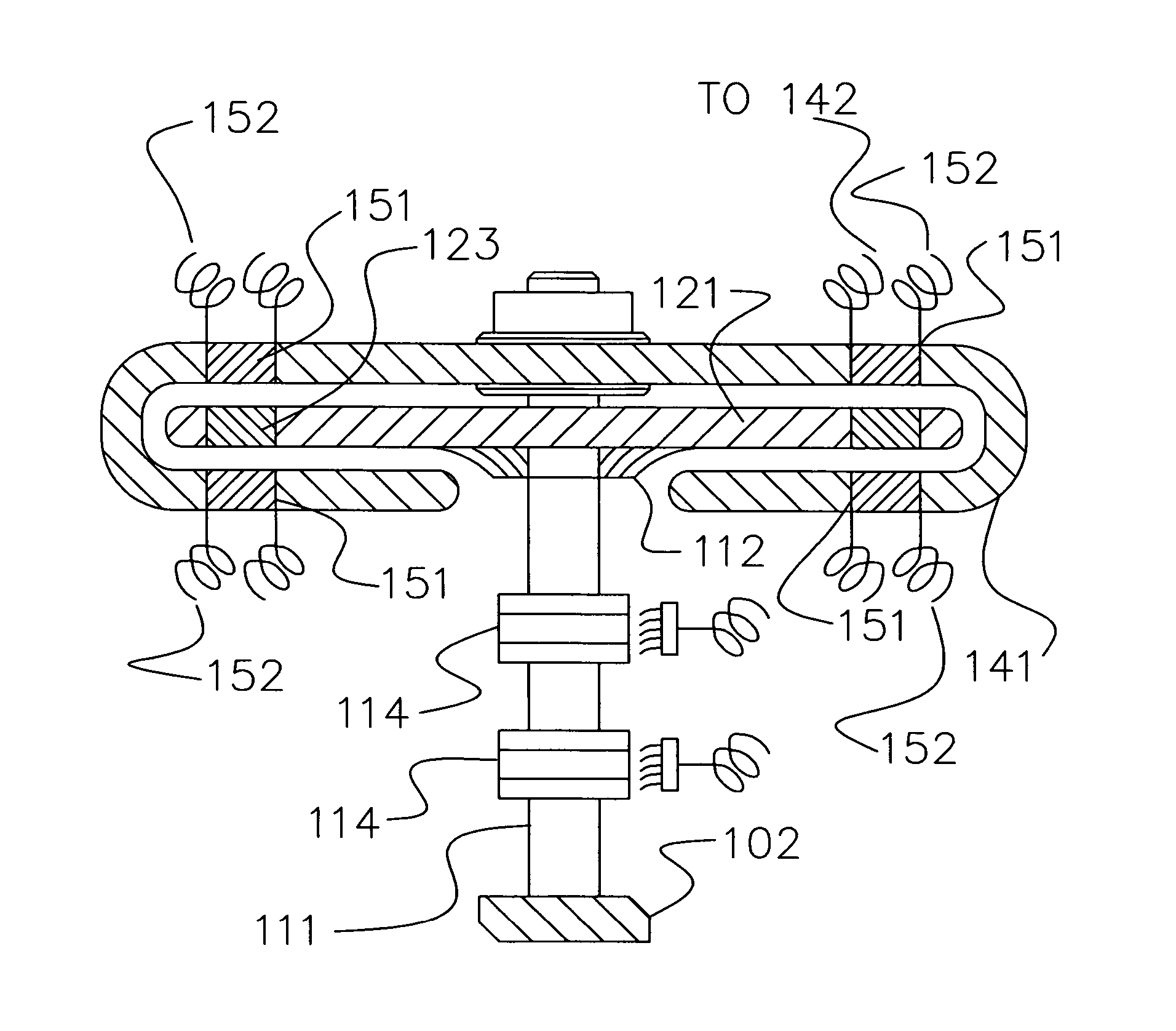
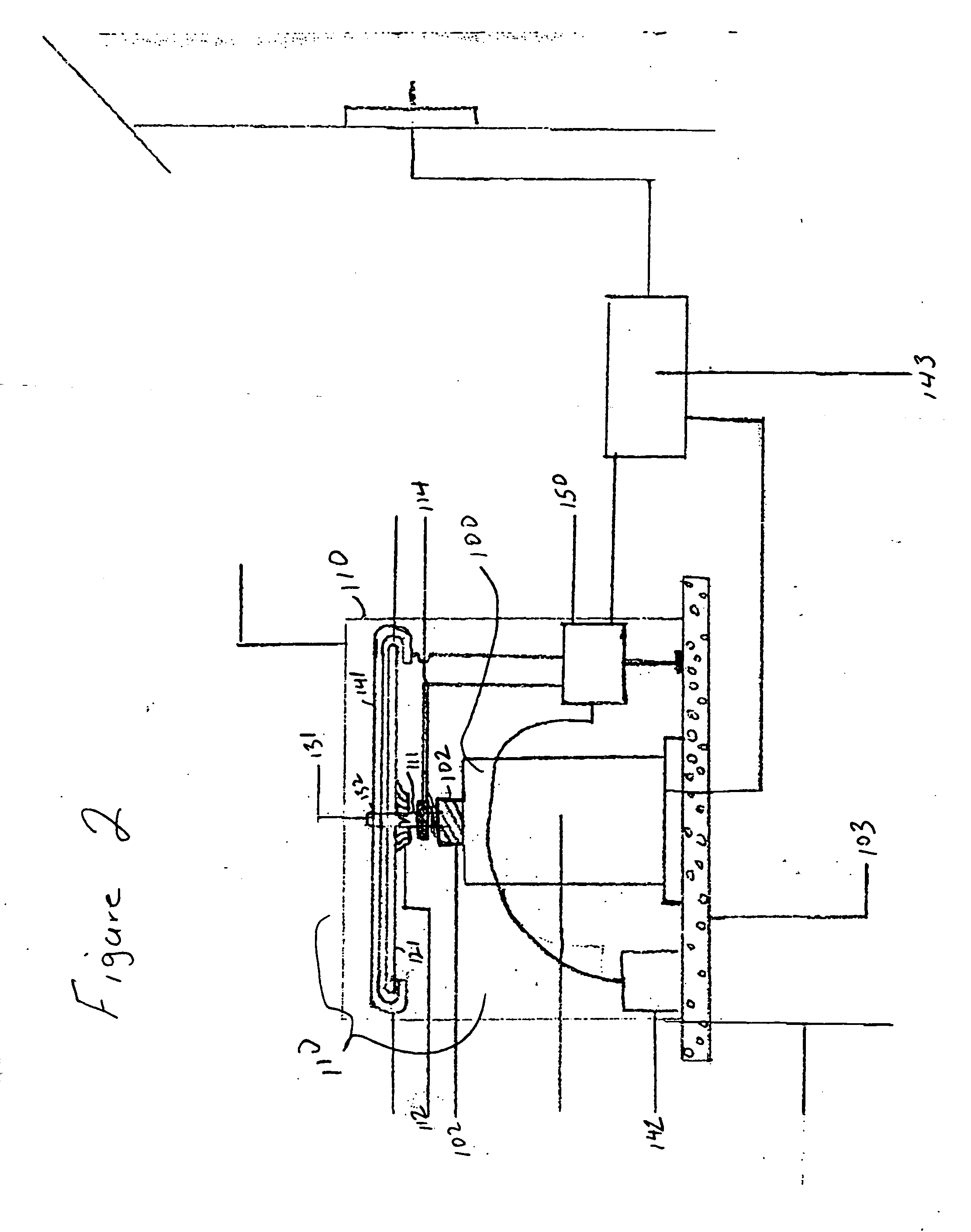
[0020] When used for electric power generation an iteration of the apparatus may provide electromagnetic coils within the generator which are turned through the power generation magnetic field by one or more rotors which extend radially from the generator shaft and upon which are mounted permanent magnets which rotate along a circumferential rail. Permanently mounted about the circumferential rail are a series of electromagnets. These electromagnets are made of a material which permits rapid magnetization and polarity reversal without significant residual magnetization or degradation of its magnetic properties.
[0023] Essentially, the invention takes advantage of a disparity in the magnetic properties between the permanent and electromagnets used in the driving magnetic paths and the magnetic properties in the permanent and electromagnets in the power generator and, in a large measure, results in a transfer of stored electricity from the permanent magnets in the rail mounted driving magnetic circuit into electricity.
[0030] It is then an object of the present invention to provide a more efficient and effective means of converting magnetic energy into rotational energy by the skillful manipulation of electrical currents and electromotive forces.
[0033] It is another object of the present invention to provide apparatus and method for producing and maintaining an alternative source of energy which is independent of fossil fuels and may, for some realistic period of time, be self-sustaining.

Problems solved by technology

What is not presently available is the application of such an array to apparatus which is actually used in generating electrical or rotational energy from the energy stored within a permanent magnet.
In the past the utility of such devices has been limited to the storage of electrical energy or to regulating the distribution or application of electrical energy.
While each application must be specifically engineered, the research performed and published to date includes specific limitations of the existing Halbach array.

Method used


Image

  • Electro-motive machine using halbach array
  • Electro-motive machine using halbach array
  • Electro-motive machine using halbach array

Examples


Embodiment Construction

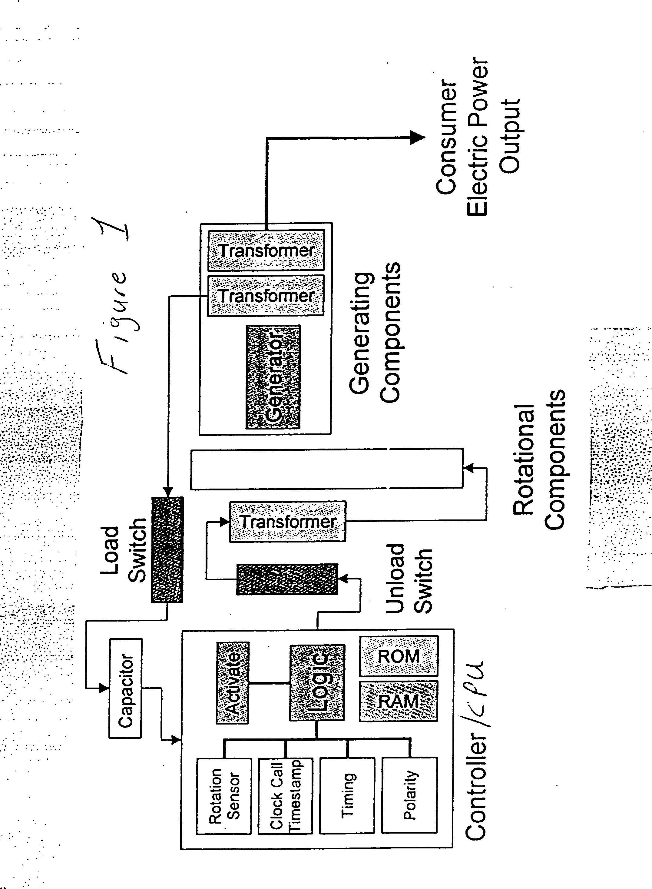
[0052] Reference will now be made in detail to the present preferred embodiment of the invention, an example of which is illustrated in the accompanying drawings and which is further described and explained by reference to the accompanying tables. While the invention will be described in connection with a preferred embodiment, it will be understood that it is not intended to limit the invention to that embodiment. On the contrary, it is intended to cover all alternatives, modifications, and equivalents as may be included within the spirit and scope of the invention defined in the appended claims.

[0053] While the following description will seek to improve understanding of the invention by describing the various components and elements, it should be considered that certain apparatus may be sufficiently and adequately explained by the accompanying drawings, which are fully incorporated herein, and not require further description. All such apparatus should be considered as part of the ...


PUM


Abstract

A Halbach array is radially disposed in an environment optimized for efficiency and controlled for efficient generation and use of power in order to generate, establish, and maintain a desired level of rotational energy with enhanced efficiency.

Description

FIELD OF THE INVENTION [0001] The invention relates to devices and methods for the generation of rotational energy from a Halbach array for the production of electricity and other useful applications. BACKGROUND OF THE INVENTION [0002] Halbach magnetic arrays have enabled electrical motors to achieve substantial new efficiencies and powers than were previously possible. Various applications of these types of magnetic arrays have included such things as the bullet train, rotational electric batteries, and a variety other mechanical and electrical devices. [0003] Since the Halbach array was first developed it has been applied to various applications in order to exploit the relationship between kinetic and electrical energy which are uniquely related and can be transitioned by magnetic fields. For instance, in U.S. Pat. No. 6,758,146 issued to Post on Jul. 6, 2004, a pair of Halbach arrays are magnetically and structurally connected so as to provide energy for propulsion of the arrays ...

Claims


Application Information

Patent Timeline
IPC IPC(8): H02K21/00
CPCH02K21/24H02K53/00H02K21/38
Inventor DUNN, TOMMCMASTERS, RICHARDEPSTEIN, MARTINHARMS, JON
Owner DUNN TOM
Learn More