
Production method of offset-shaped fins, fins, and method and apparatus for changing pitch of fins

a production method and fin technology, applied in the direction of lighting and heating equipment, laminated elements, tubular elements, etc., can solve the problems of difficult roll molding practice, material damage to rollers, and inability to achieve heat transfer efficiency improvement, etc., to achieve stably and continuously produced fins, the effect of reducing production cost and installation area

Inactive Publication Date: 2007-02-08
DENSO CORP
View PDF5 Cites 23 Cited by
  • Summary
  • Abstract
  • Description
  • Claims
  • Application Information

AI Technical Summary

Benefits of technology

[0014] It is a second object of the invention to provide a pitch changing method, and a pitch changing apparatus, that can reliably reduce or expand a pitch of wide offset-shaped fins produced in advance by roll molding, etc, to a desired pitch, and can minimize variance of the fin pitch per crest.
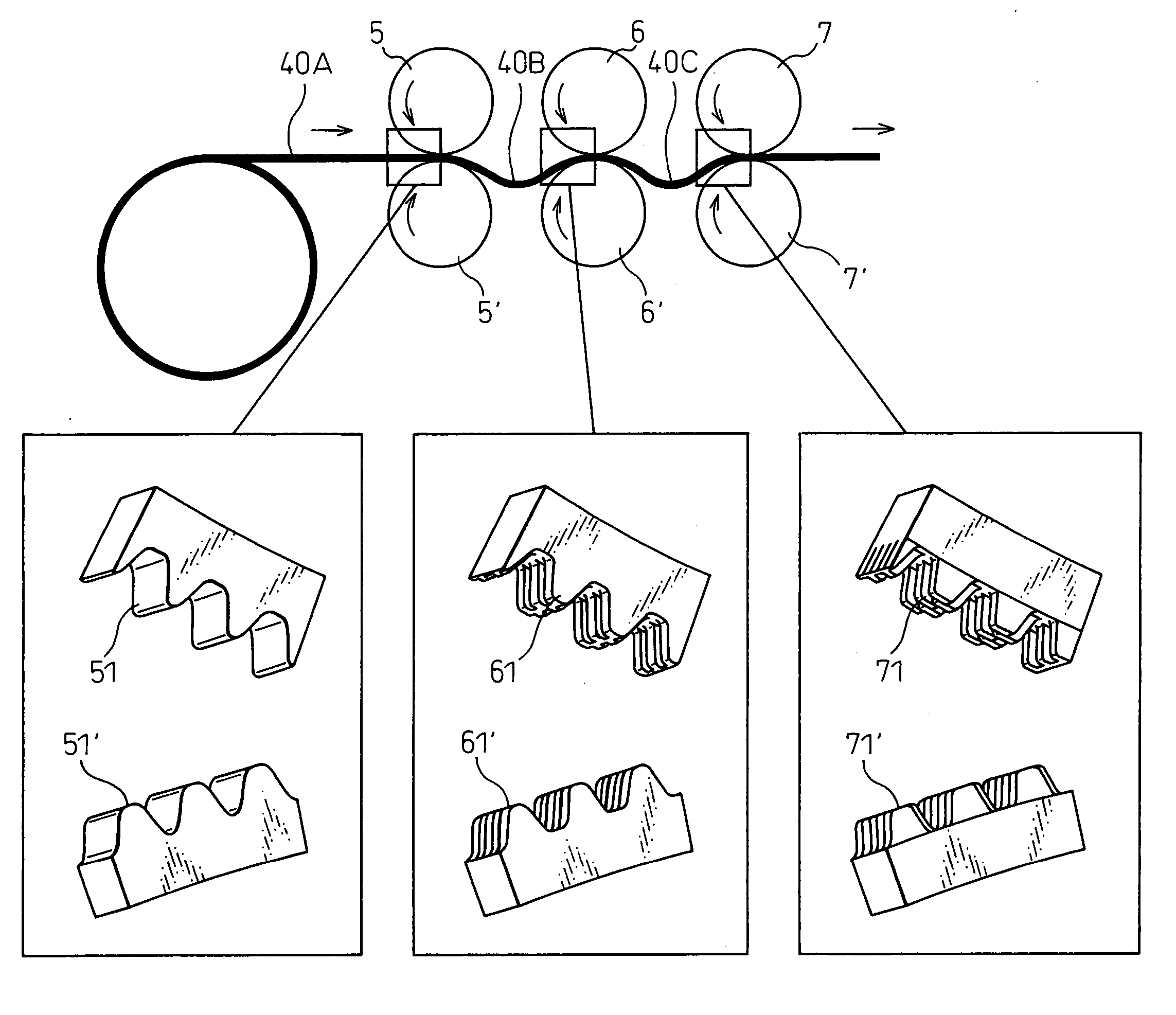
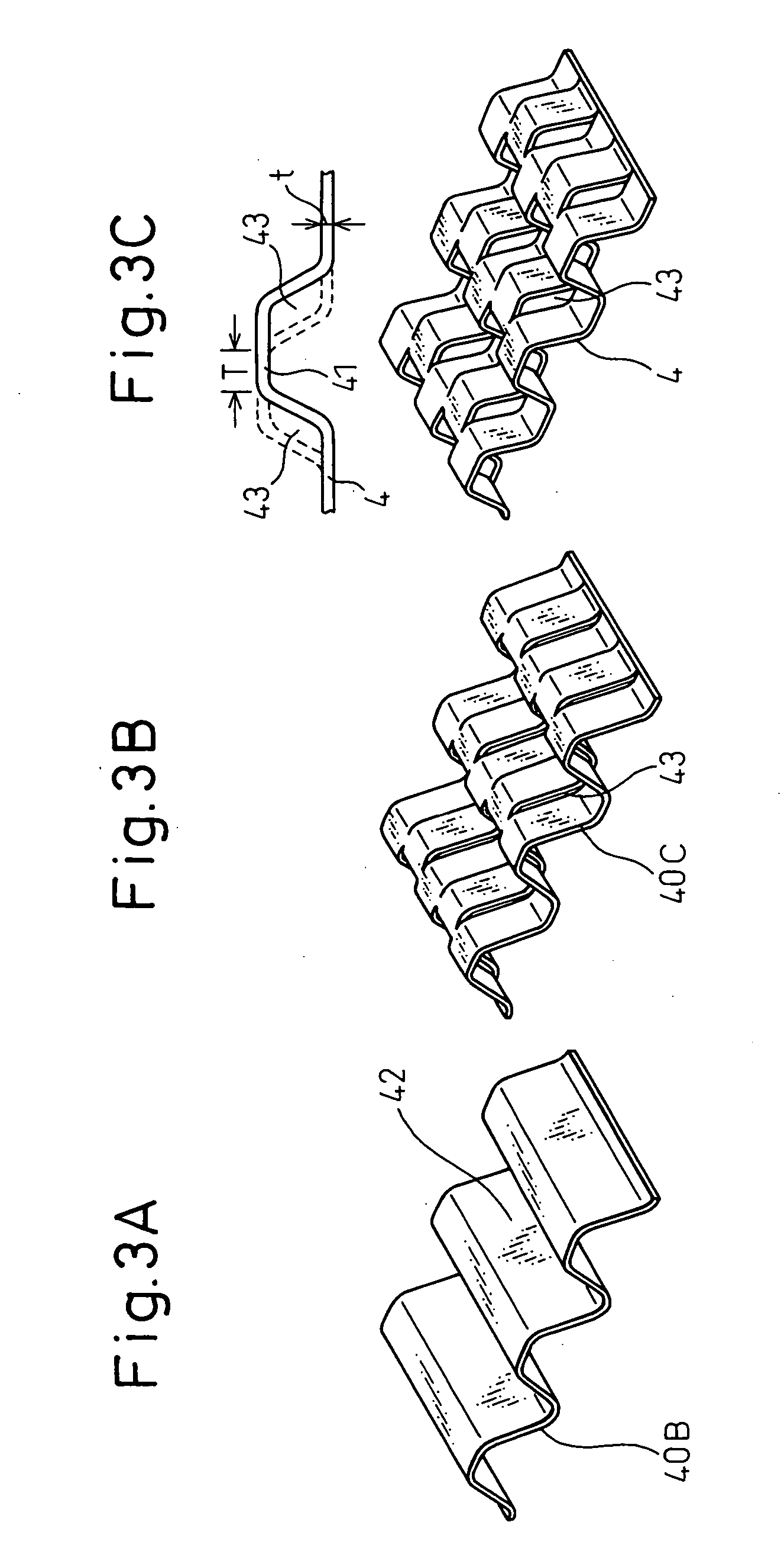
[0015] According to one aspect of the present invention, there is provided a production method of offset-shaped fins including a first step of bending a flat sheet-like material 40A into a concavo-convex shape by a pair of first rollers 5 and 5′ having concavo-convex ridges 51 and 51′ formed on the surface thereof to form a corrugate sheet 40B; a second step of cutting slopes of the concavo-convex ridges 42 of the corrugate sheet by a pair of second rollers 6 and 6′ having cutting edges 61 and 61′ arranged in an offset arrangement to form an offset portion 43; and a third step of bending the offset portion 43 offset and cut in the second step by a pair of third rollers 7 and 7′ having concavo-convex ridges 71 and 71′ arranged in an offset arrangement on the surface thereof. Consequently, the offset-shaped fins 4 can be produced stably and continuously by roll molding without catch and breakage of the material and the production cost as well as the installation area can be reduced.
[0016] In the production method of the offset-shaped fins according to the invention, an offset amount D (see FIG. 5) of the cutting edges in the second step is set to about a sheet thickness so that catch of the cut material into the rollers is approximately the same as the sheet thickness. In this way, the peeling property of the material from the rollers can be improved and catch and breakage of the material can be suppressed.
[0017] In the production method of the offset-shaped fins according to the invention, gaps G (see FIG. 6) are disposed between bent teeth offset and arranged in the third step so as to avoid contact of the material with the rollers. Consequently, the peeling property of the material from the rollers can be improved and penetrating and breakage of the material can be suppressed.
[0018] In the production method of the offset-shaped fins according to the invention, intermediate rollers 8 for guiding the sheet material under molding are arranged between the first roller 5, 5′ and the second roller 6, 6′ and between the second roller 6, 6′ and the third roller 7, 7′. Accordingly, the intermediate roller 8 guides the sheet material and can limit its movement, and stable roll molding of the offset-shaped fins 4 can be conducted.
[0022] According to the construction described above, each tooth shape of at least one pair of pitch changing rollers, in particular, is substantially similar to the profile shape of the transverse section of the offset-shaped fins on each roller side in the traveling direction of the offset-shaped pins after the pitch change by one pair of pitch changing rollers. Therefore, the pitch of the offset-shaped fins can be reliably changed to a predetermined and desired pitch by causing at least one pair of pitch changing rollers to clamp the offset-shaped fins between them, by passing the offset-shaped fins through the pitch changing rollers and by changing their pitch, and the variance of the pitch per crest can be suppressed to minimum. When the pitch changing method and the pitch changing apparatus according to the invention are combined with the production line of the offset-shaped fins by roll molding, the speed of production of the offset-shaped fins having a desired fin pitch and extremely little variance of the fin pitch per crest can be increased, and the production cost, the installation cost, installation area and the energy cost can be drastically reduced.

Problems solved by technology

Therefore, an improvement in heat transfer efficiency cannot be expected.
Another problem is that the material damages the rollers.
Therefore, it has been ordinary knowledge that roll molding is difficult to practice.
However, the system of Japanese Unexamined Patent Publication No. 2001-221588 in which the offset portion is bent into the trapezoidal shape after processing by applying cutting and bending is limited to the case where the length T of the coupling portion A with the adjacent convex portion offset is smaller than the thickness t of the material as shown in Fig. 1OC.
In addition, penetrating the material into the rollers and breakage at the coupling portion A may occur because the cut amount is large and the coupling portion A undergoes large deformation during the subsequent bending work (slope portion → flat portion).
Thus, stable processing cannot be expected.
Particularly when offset-shaped fins, used for heat exchangers, etc, are roll molded, the tooth shape is not established if the pitch fin is too short because the inclination of the crest portion of the fin becomes too acute.
Each of these references can suppress the variance of the mean fin pitch per unit length but cannot suppress the variance of the fin pitch per crest.
Because the contact between the gear and the fin is a point contact, the technology is suitable for a corrugate fin having a small width, but cannot be easily applied to the offset-shaped fin having a large width.
When the fin pitch of the inner fins for a radiator, that have been produced in advance by roll molding, etc, is changed to a desired pitch at the time of the practical use as described above, the prior art technology involves the problem that offset-shaped fins having a large width cannot be reliably changed to the desired fin pitch while minimizing the variance of the fin pitch per crest.

Method used


Image

  • Production method of offset-shaped fins, fins, and method and apparatus for changing pitch of fins
  • Production method of offset-shaped fins, fins, and method and apparatus for changing pitch of fins
  • Production method of offset-shaped fins, fins, and method and apparatus for changing pitch of fins

Examples


Embodiment Construction

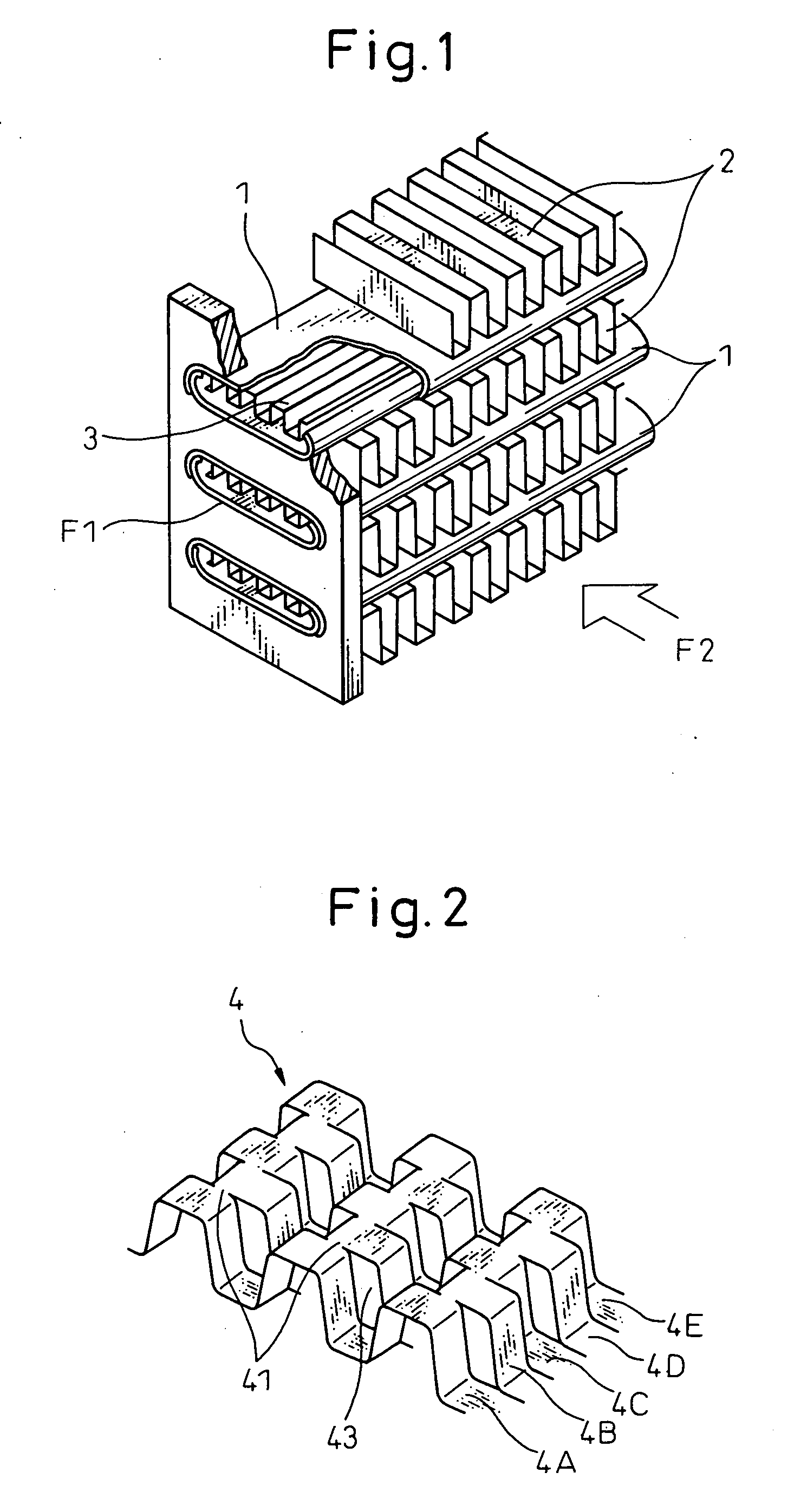
[0038] A production method of offset-shaped fins according to the present invention and the offset-shaped fins produced by this production method will be explained hereinafter with reference to the accompanying drawings. FIG. 1 shows an example of a stacked type heat exchanger. In the stacked type heat exchanger, a plurality of heat transfer tubes 1 are extended in parallel with one another between a pair of headers not shown, and corrugate fins (outer fins) 2 are arranged between the heat transfer tubes 1. In other words, a heat exchange core portion is formed as the heat transfer tubes 1 and the outer fins 2 are alternately stacked. Consequently, heat exchange is made between a heat exchange medium F1 flowing inside the heat transfer tubes 1 and a heat exchange medium F2 passing through the outer fins 2 outside the heat transfer tubes 1.

[0039] In this case, it has been customary to insert and arrange inner fins 3 into the heat transfer tube 1, as shown in FIG. 1, in order to prom...


PUM

PropertyMeasurementUnit
Currentaaaaaaaaaa
Digital informationaaaaaaaaaa
Thicknessaaaaaaaaaa

Abstract

An offset-shaped fin 4 can be continuously processed by roll molding by a method involving a first step of bending a flat sheet-like material 40A into a concavo-convex shape by a pair of first rollers 5, 5′ to form a corrugate sheet 40B; a second step of cutting slopes of the concavo-convex ridges of the corrugate sheet by a pair of second rollers; and a third step of bending the offset portion, offset and cut in the second step, by a pair of third rollers. A pitch-changing method of offset-shaped fins involves a step of supplying offset-shaped fins between at least one pair of pitch-changing rollers rotating while meshing with the other so that at least one pair of pitch-changing rollers clamp the offset-shaped fins between them, allow them to pass through said pitch-changing rollers and change their pitch.

Description

BACKGROUND OF THE INVENTION [0001] 1. Field of the Invention [0002] This invention relates to a production method for producing offset-shaped fins, that are acquired by offsetting a corrugation shape of corrugate fins by roller molding, the offset-shaped fins produced by this production method, and a method, and an apparatus for the method, for changing the pitch of the offset-shaped fins that are produced in advance by roll molding, etc, particularly those which are used for inner fins of an oil cooler for a radiator, by increasing or decreasing the pitch to a desired pitch to be actually used. [0003] 2. Description of the Related Art [0004] A stacked type heat exchanger that is produced by alternately stacking a plurality of conduit lines and corrugated fins (outer fins) to form a heat exchange core and causes heat exchange between a heat exchange fluid flowing inside the conduit lines and a heat exchange fluid flowing outside the conduit lines is well known. To improve heat trans...

Claims


Application Information

Patent Timeline
IPC IPC(8): F28F13/12B21D13/00
CPCB21D31/046F28F3/027F28F1/128
Inventor TESHIMA, KUNIHARUMITSUKAWA, KAZUHIROKUROKI, YASUSHIYAMAUCHI, TAKUMIKACHI, KENICHI
Owner DENSO CORP
Learn More