
Apparatus and method for color dithering

a color dithering and apparatus technology, applied in the direction of static indicating devices, instruments, cathode-ray tube indicators, etc., can solve the problems of deteriorating performance, limited color depth display, and limited spatial and temporal periods of conventional dithering methods, so as to reduce the interaction with the circuit, prevent percevable dithering noise, and efficiently implement color dithering

Inactive Publication Date: 2007-02-01
NOVATEK MICROELECTRONICS CORP
View PDF3 Cites 17 Cited by
  • Summary
  • Abstract
  • Description
  • Claims
  • Application Information

AI Technical Summary

Benefits of technology

[0010] Accordingly, the objective of the present invention is for providing an apparatus and method thereof for color dithering, which efficiently implements color dithering having extended period for preventing perceivable dithering noise, or for reducing the interaction with the circuit or system characteristics variation which will decreases image quality.
[0016] According to the present invention, whether to carry is determined according to a random number. The random number generator can de achieved with low cost while keeping the long period. Thus the present invention is able to prevent perceivable color dithering noise and the annoying fluctuation caused by regular input video signal or undesired interaction with system configuration and circuitry. Moreover, the present invention is can be easily integrated with the conventional table look-up method to gain the advantages.

Problems solved by technology

However, conventional visual output apparatuses such as displays, projectors, printers, etc, are limited in the exhibition of color depth at for example only 64 color levels due to the consideration of hardware cost.
However, no matter whether it is static dithering or dynamic dithering, due to the limit in the complexity and the cost of the circuitry or the dithering algorithm, the conventional dithering methods' spatial and temporal periods are usually quite limited.
The short period in time and space are easily tracked and predicted by human perception thus results in deteriorated performance.
Besides, sometimes the input signal has its own spatial period such as dot Moire and line Moire video test pattern, and also in some systems, as an example, in liquid crystal displays (LCD), the properties of each pixel are not necessary identical due to some electrical characteristics variation in production, which will cause some undesired periodic variation in time and space.
Moreover, the inversion method (dot line and frame inversion) used in LCD driver will often leads to some degree of asymmetry, therefore results in periodical fluctuation in space and time.
Once the aforementioned system periodical fluctuation interacts with the periodical variation due to dithering, the dithering noise will becomes more visually perceivable and leads to flickering, thus may degrade image quality.
It will be quite unacceptable for human eyes.

Method used


Image

  • Apparatus and method for color dithering
  • Apparatus and method for color dithering
  • Apparatus and method for color dithering

Examples


Embodiment Construction

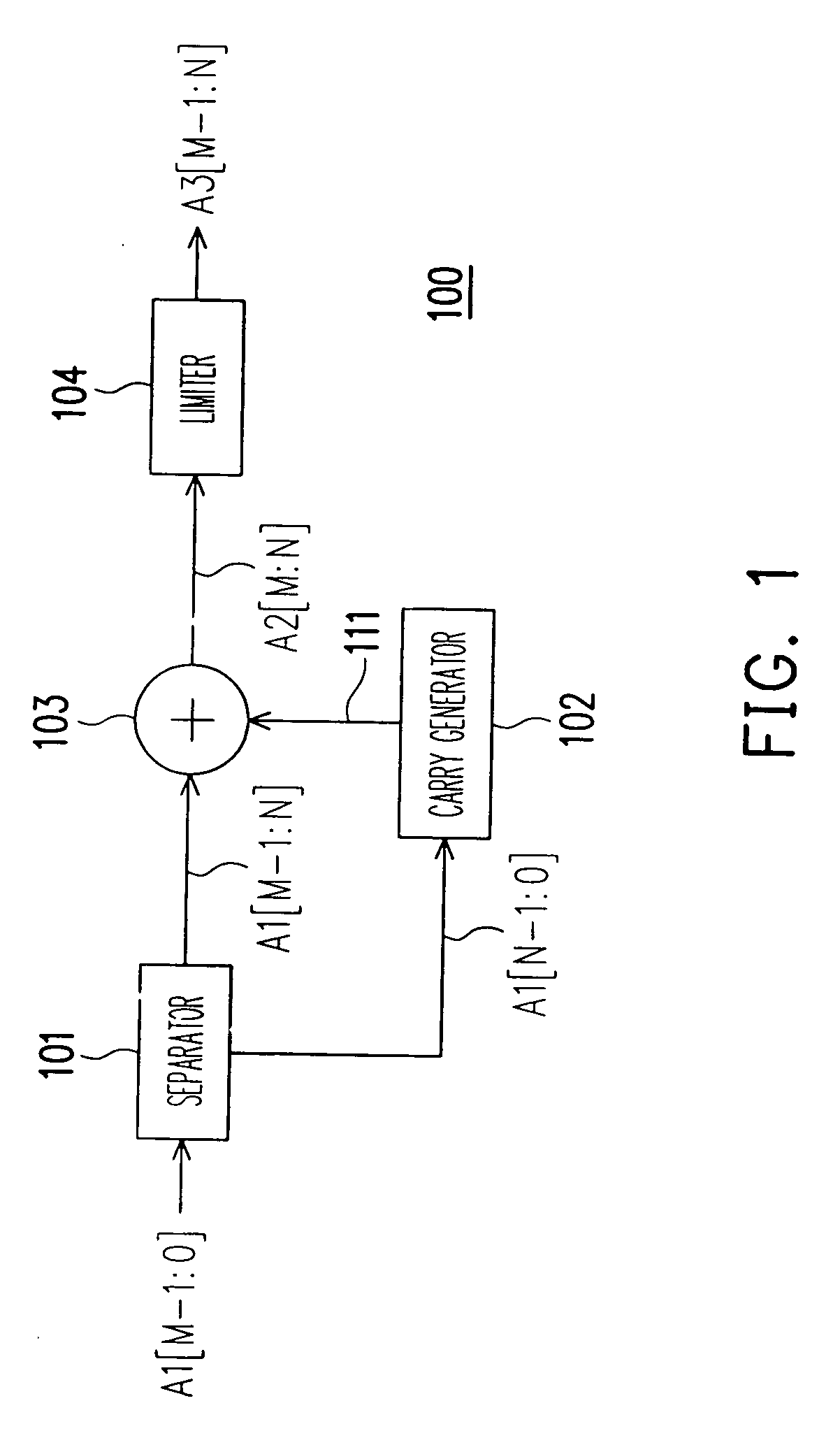
[0022] In the following description, it is assumed that the color resolution of the signal source is M bits, and the color resolution of the output apparatus is M−N bits. M and N are both positive integers, and M>N>=1.

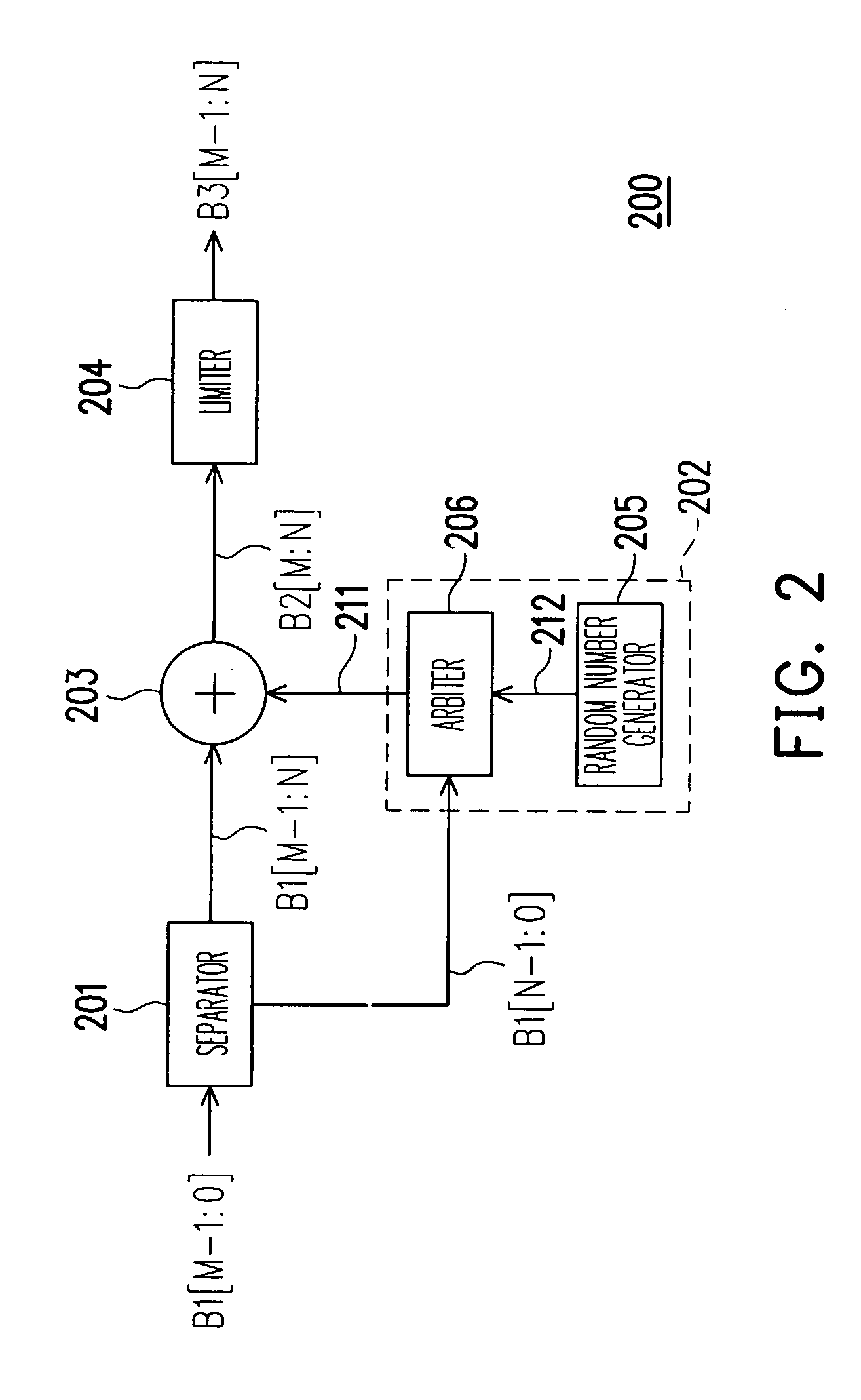
[0023] An embodiment of the present invention is described in FIG. 2, which is a block diagram illustrating the color dithering apparatus 200, according to the present embodiment of the present invention. The color dithering apparatus 200 includes a separator 201, a carry generator 202, an adder 203, and a limiter 204. First, the separator 201 receives a M-bit color value B1[M−1:0] and separates the color value B1[M−1:0] into a high-bit color value B1[M−1:N] and a low-bit color value B1[N−1:0]. In which, the low-bit color value B1[N−1:0] includes N LSBs of color value B1[M−1:0] and the high-bit color value B1[M−1:N] includes M−N MSBs of color value B1[M−1:0].

[0024] Next, the carry generator 202 provides a carry value 211 according to a random number and the low-bit c...


PUM


Abstract

An apparatus and the method which implement color dithering having an extended period for preventing perceivable dithering noise caused by the asymmetry and un-ideal characteristics existing in a display system are provided. The apparatus includes a separator, a carry generator, an adder and a limiter. The separator receives a color value and separates the color value into a high-bit color value and a low-bit color value. Then the carry generator provides a carry value to be either one or zero, according to a random number from a random number generator and the low-bit color value. The adder adds the high-bit color value and the carry value, and provides the result as a tentative output value. Finally, the limiter receives the tentative output value and outputs the smaller value of the tentative output value and a pre-set upper limit.

Description

CROSS-REFERENCE TO RELATED APPLICATION [0001] This application claims the priority benefit of Taiwan application serial no. 94126012, filed on Aug. 1, 2005. All disclosure of the Taiwan application is incorporated herein by reference. BACKGROUND OF THE INVENTION [0002] 1. Field of Invention [0003] The present invention relates to an apparatus and method for color dithering. More particularly, the present invention relates to a color dithering apparatus and method thereof which determines whether to carry to the higher digit based on a random number. [0004] 2. Description of Related Art [0005] Today, visual signal sources generated from integrated circuits, and software of computers and videos are capable to produce more and more color levels, for example, 256 color levels with 8-bit resolution or 1024 color levels with 10-bit resolution. However, conventional visual output apparatuses such as displays, projectors, printers, etc, are limited in the exhibition of color depth at for ex...

Claims


Application Information

Patent Timeline
Patent Type & Authority Applications(United States)
IPC IPC(8): G09G5/02
CPCG09G3/2048G09G3/2003
Inventor LO, JUI-LIN
Owner NOVATEK MICROELECTRONICS CORP
Learn More