
Catalyst withdrawal apparatus and method for regulating catalyst inventory in a fluid catalyst cracking unit

a technology of fluid catalytic cracking and catalyst inventory, which is applied in the direction of lighting and heating apparatus, instruments, furniture, etc., can solve the problems of catalyst bed level within the regenerator reaching an upper operating limit, reducing the performance and desired output and affecting the operation of the fcc uni

Active Publication Date: 2007-01-25
JOHNSON MATTHEY PROCESS TECH
View PDF15 Cites 58 Cited by
  • Summary
  • Abstract
  • Description
  • Claims
  • Application Information

AI Technical Summary

Problems solved by technology

If the amount of catalyst within the FCC unit diminishes over time, the performance and desired output of the FCC unit will diminish, and the FCC unit will become inoperable.
Conversely, if the catalyst inventory in the FCC unit increases over time, the catalyst bed level within the regenerator reaches an upper operating limit, necessitating a small catalyst withdrawal to prevent unacceptably high catalyst emissions into the flue gas stream, or other process upsets.
Because these sudden changes in regenerator bed level cause changes in the pressure balance of the FCC unit, they may result in changes in catalyst circulation rate, reactor temperature and / or regenerator temperature, and these upset the stability of the FCC unit operation.
As these changes in the dynamic equilibrium force the FCC unit away from its operating limits, the desired product mix and / or effluent composition may not be obtained.
Anything that forces the operation of the FCC unit away from these limits reduces profitability and is a major detriment to the refiner.

Method used


Image

  • Catalyst withdrawal apparatus and method for regulating catalyst inventory in a fluid catalyst cracking unit
  • Catalyst withdrawal apparatus and method for regulating catalyst inventory in a fluid catalyst cracking unit
  • Catalyst withdrawal apparatus and method for regulating catalyst inventory in a fluid catalyst cracking unit

Examples


Embodiment Construction

[0021] The invention generally provides catalyst withdrawal apparatus suitable for use on a fluid catalyst cracking (FCC) unit and a method for regulating catalyst inventory in a FCC unit. Advantageously, the invention facilitates the removal of excess catalysts from the FCC unit with minimal process disruption.

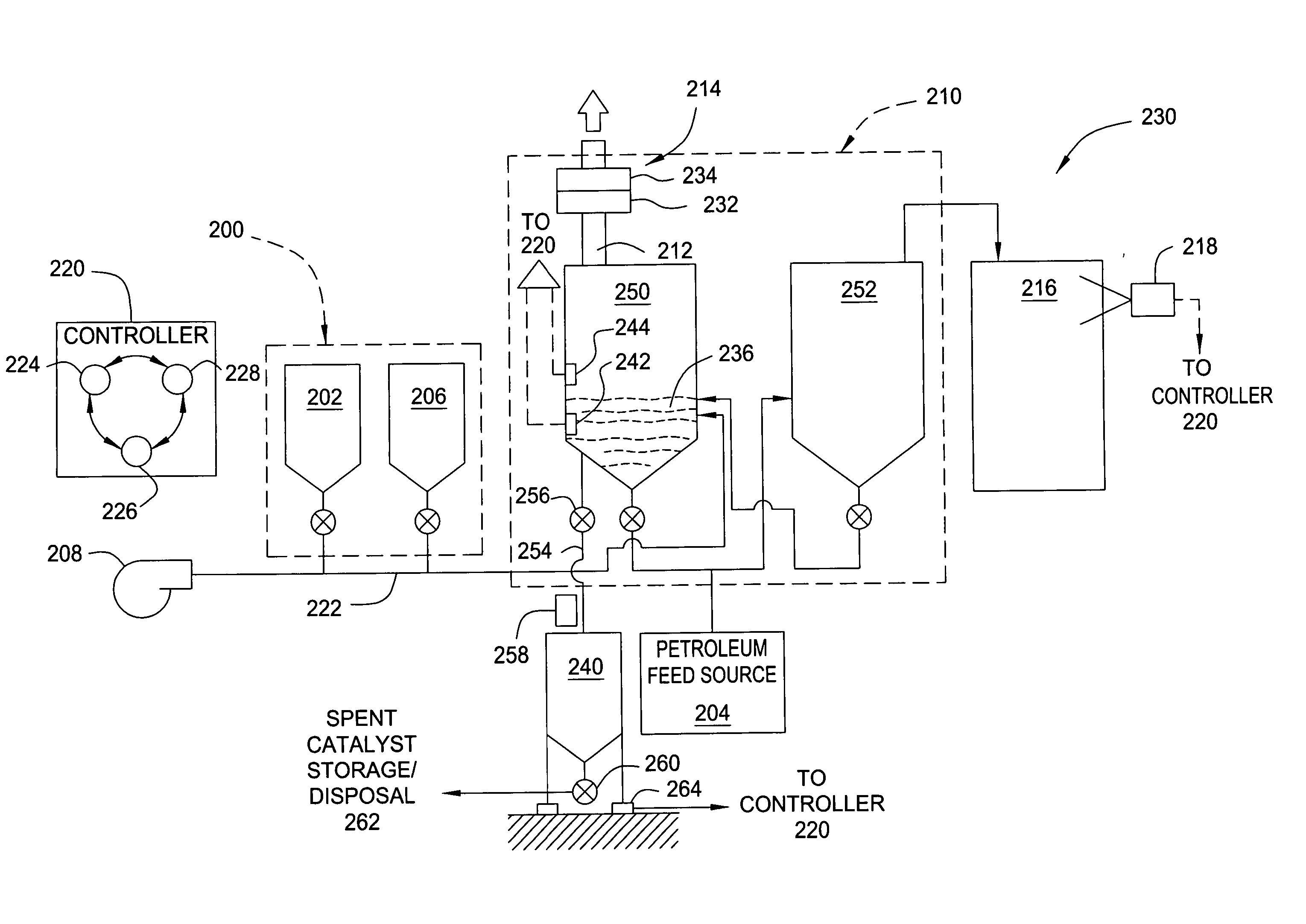
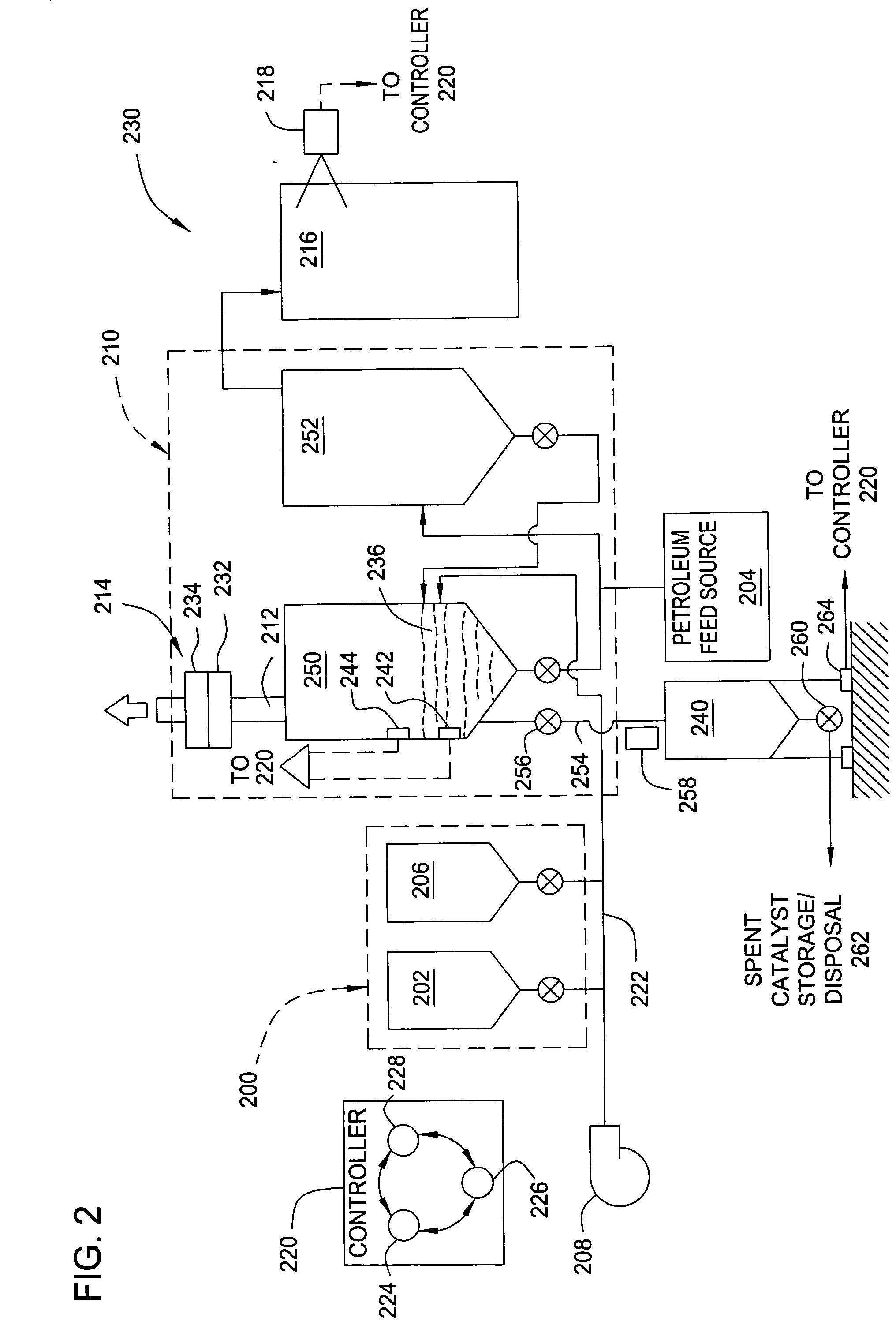
[0022]FIG. 2 is a simplified schematic of a fluid catalytic cracking system 230 having a metered catalyst withdrawal system 240. The fluid catalytic cracking system 230 generally includes a fluid catalytic cracking (FCC) unit 210 coupled to a catalyst injection system 200 and the metered catalyst withdrawal system 240, a controller 220, a petroleum feed stock source 204, an exhaust system 214 and a distillation system 216. One or more catalysts from the catalyst injection system 200 and petroleum from the petroleum feed stock source 204 are delivered to the FCC unit 210. The petroleum and catalysts are reacted in the FCC unit 210 to produce a vapor that is collected and sepa...


PUM

PropertyMeasurementUnit
Pressureaaaaaaaaaa
Temperatureaaaaaaaaaa
Pressureaaaaaaaaaa

Abstract

A catalyst withdrawal apparatus and method for regulating catalyst inventory in a fluid catalytic cracking catalyst (FCC) unit is provided. In one embodiment, a catalyst withdrawal apparatus for removing catalyst from a FCC unit includes a pressure vessel having a metering device coupled to a fill port. A heat dissipater is located adjacent the metering device and is adapted to cool catalyst entering the pressure vessel. A sensor is coupled to the pressure vessel arranged to provide a metric indicative of catalyst entering the pressure vessel through the metering device. In another embodiment, a method for regulating catalyst inventory in a FCC unit includes the steps of determining a change of catalyst present in a FCC unit, withdrawing catalyst from the FCC unit into an isolatable storage vessel coupled to the FCC unit, measuring the amount of catalyst disposed in the storage vessel, and removing the measured catalyst from the storage vessel.

Description

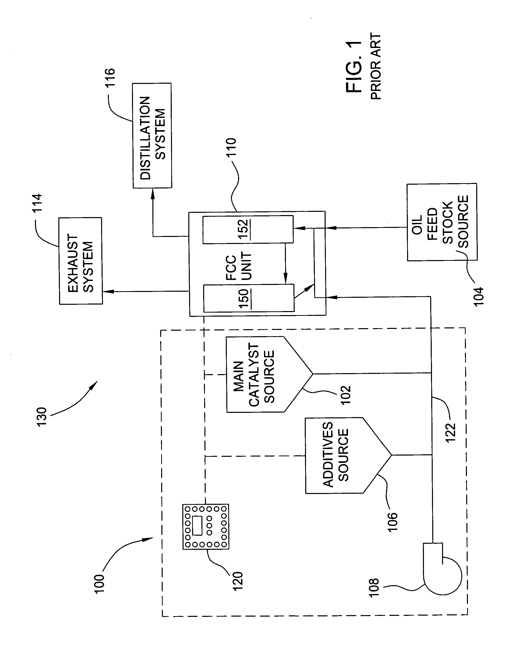
BACKGROUND OF THE INVENTION [0001] 1. Field of the Invention [0002] Embodiments of the invention generally relate to a catalyst withdrawal apparatus and method for regulating catalyst inventory in a fluid catalytic cracking catalyst unit. [0003] 2. Description of the Related Art [0004]FIG. 1 is a simplified schematic of a conventional fluid catalytic cracking system 130. The fluid catalytic cracking system 130 generally includes a fluid catalytic cracking (FCC) unit 110 coupled to a catalyst injection system 100, a petroleum feed stock source 104, an exhaust system 114 and a distillation system 116. One or more catalysts from the catalyst injection system 100 and petroleum from the petroleum feed stock source 104 are delivered to the FCC unit 110. The petroleum and catalysts are reacted in the FCC unit 110 to produce a vapor that is collected and separated into various petrochemical products in the distillation system 116. The exhaust system 114 is coupled to the FCC unit 110 and is...

Claims


Application Information

Patent Timeline
IPC IPC(8): F27B15/00B32B27/12
CPCB01J8/003C10G2300/70B01J8/0055B01J8/20B01J2208/00176B01J2208/00185B01J2208/00203B01J2208/00212B01J2208/00371B01J2208/00539B01J2208/00548B01J2208/0061B01J2208/00619B01J2208/00734B01J2208/00761B01J2208/00769B01J2219/00207B01J2219/0022B01J2219/00236C10G11/18C10G11/187B01J8/0035
Inventor EVANS, MARTIN
Owner JOHNSON MATTHEY PROCESS TECH
Learn More