
System and Methods for Organic Material Conversion and Energy Generation

a technology of organic material and conversion method, applied in the direction of energy input, combustion type, lighting and heating apparatus, etc., can solve the problems of insufficient mixing of material, inability to independently control the speed and amount of mixing with time, and the production of reaction water

Inactive Publication Date: 2007-01-18
WINTERBROOK INVESTMENT PARTNERS
View PDF22 Cites 11 Cited by
  • Summary
  • Abstract
  • Description
  • Claims
  • Application Information

AI Technical Summary

Benefits of technology

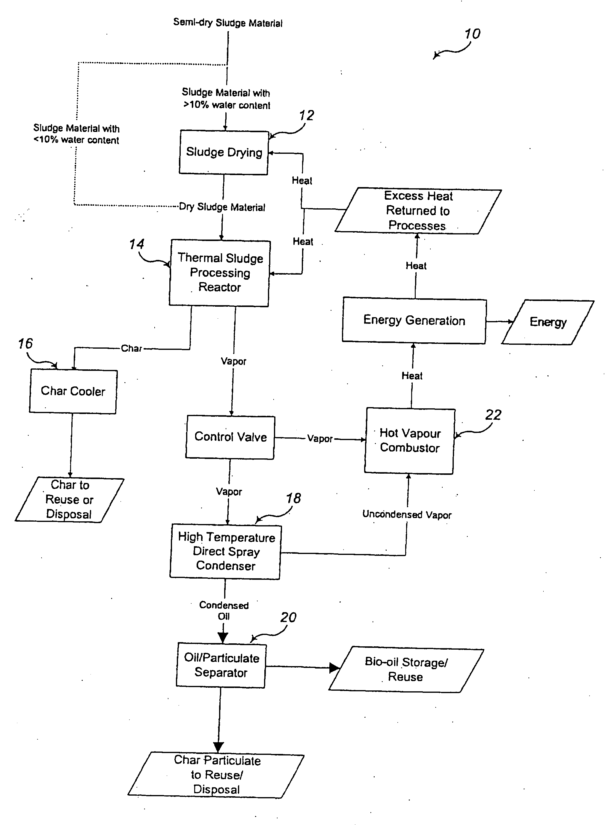
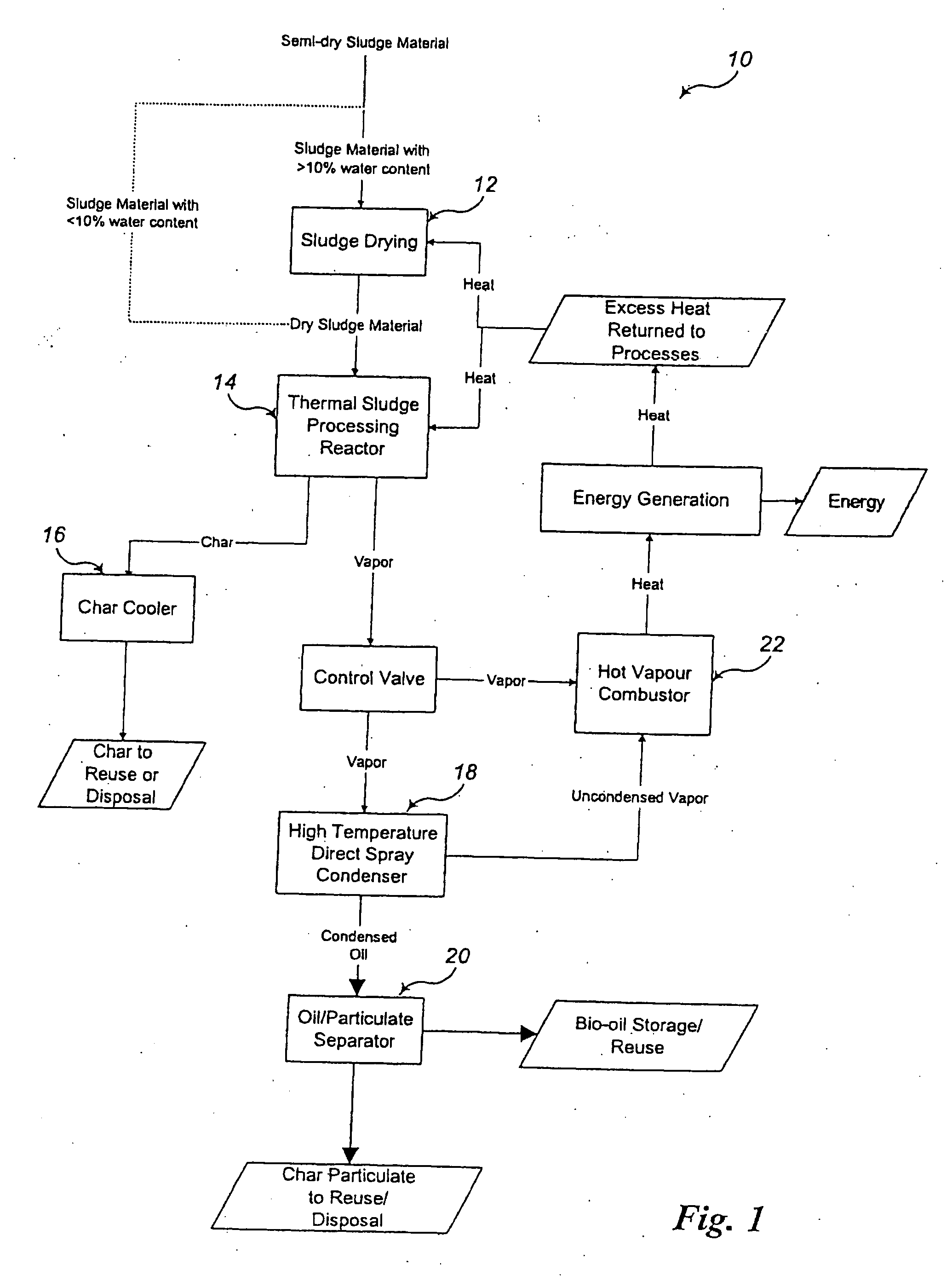
[0025] As stated, one major drawback of the prior art is the production of reaction water due to the presently used condensation methods and resulting need for three-phase centrifugal separation of oil, particulate matter and reaction water. The present invention provides methods to avoid the production of reaction water, thus requiring only a two-phase centrifugal separation of oil and particulate matter and avoiding inefficiencies and environmental issues associated with reaction water. The present invention avoids the production of reaction water by condensing oils at a temperature above that at which water will condense. In one embodiment, this benefit is achieved by condensing oil with other oil cooled enough to condense additional oil but not cooled enough to condense water. This advance removes the numerous drawbacks associated with the production of reaction water that currently exist in presently used pyrolysis methods.
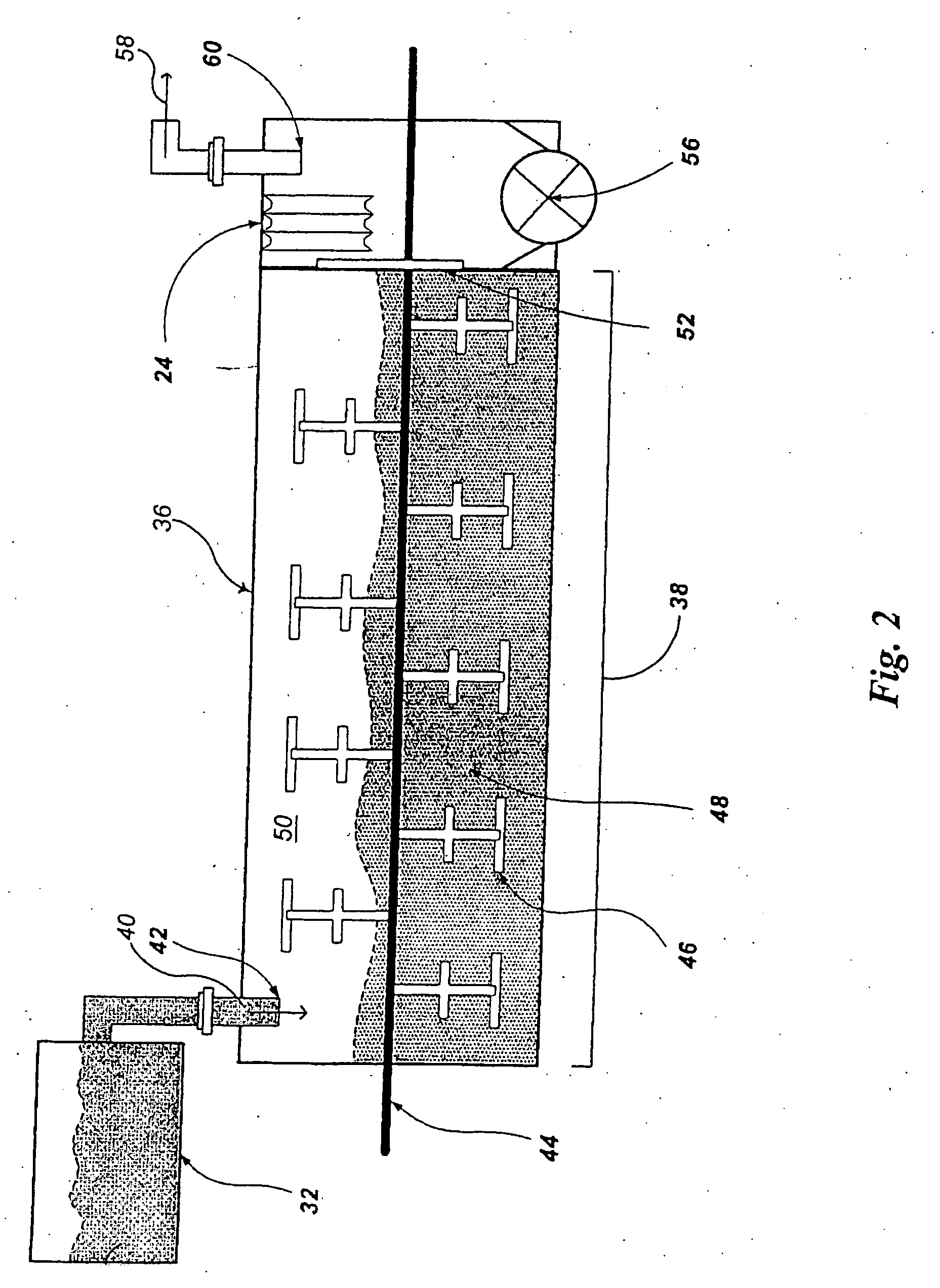
[0027] The present invention addresses these particular drawbacks by adopting mixing elements that can increase contact between sludge and vapors as the sludge moves through a reaction chamber (and becomes char) but do not convey the sludge / char material through the reaction chamber. By separating the function of conveying material through the reaction chamber and mixing the materials, various advantages are obtained including the advantage that operators can independently control time in the reaction chamber versus amount of mixing while in the chamber. This allows adjustment during sludge processing so that batch processing can be avoided. This approach also allows greater fill coefficients of the reaction chamber because, irregardless of the amount of mixing that occurs, the sludge and / or char can remain in the reactor chamber for any desired period of time. Thus, separating time spent in the chamber from the amount of mixing can increase contact between the shell and contents of the chamber to facilitate efficient heat transfer and production of quality bio-oil and / or chars. In one embodiment, adjustments can also occur through automated controls while the pyrolysis process remains on-going. The present invention also provides numerous other benefits over prior art approaches that will become clear through the entirety of the present disclosure.
[0036] Methods according to the present invention can further comprise mixing the sludge, the vapors and the char in the reaction chamber with mixing elements thereby increasing contact between the sludge, the vapors and the char within the reaction chamber.

Problems solved by technology

As stated, one major drawback of the prior art is the production of reaction water due to the presently used condensation methods and resulting need for three-phase centrifugal separation of oil, particulate matter and reaction water.
An additional drawback of the prior art is that conveyance of sludge through a reaction chamber occurred so slowly that the material was not mixed sufficiently during the process to allow sufficient contact between the sludge and vapors in the reaction chamber.
While this approach addressed the previous issue of insufficient mixing, it produced drawbacks of its own including the inability to independently control speed and amount of mixing with time of sludge in the reaction chamber and the need to calculate paddle parameters before the reactor was put into service (with an inability to readily adjust these parameters thereafter).
Further with this approach, it was difficult to keep sludge from accumulating in certain areas of the reactor causing a torque overload on the rotating shaft and paddles.

Method used


Image

  • System and Methods for Organic Material Conversion and Energy Generation
  • System and Methods for Organic Material Conversion and Energy Generation
  • System and Methods for Organic Material Conversion and Energy Generation

Examples


Embodiment Construction

[0052] Industrial and municipal wastewater treatment plants produce significant amounts of sludge that must be properly treated for disposal. Thermal conversion processes such as pyrolysis can be used to convert sludge into bio-oil and char that can have a wide variety of commercial and industrial applications. However, prior approaches to these processes have suffered from many drawbacks. Some of these drawbacks include the creation of reaction water and the inability to independently control the mixing of sludge material within a reaction chamber and the time the sludge spends within the reaction chamber. This particular drawback requires that operation be conducted in batches whereby a batch of sludge material is fully processed before the quality of the resulting oil can be tested. This batch process is time consuming and, when adjustments are needed, requires that the entire pyrolysis process be shut down while manually actuated valves, screws, and other moving parts are adjust...


PUM

PropertyMeasurementUnit
Temperatureaaaaaaaaaa
Areaaaaaaaaaaa

Abstract

Disclosed herein are systems and methods for thermal conversion of sludge into fuel and other products such as char. The systems and methods disclosed herein, among other benefits, convert sludge into fuel without the creation of reaction water and allow for the independent control of mixing and the movement of sludge through pyrolysis systems. Chars formed during pyrolysis have a number of beneficial uses.

Description

CROSS REFERENCES TO RELATED APPLICATIONS [0001] The present application is a continuation-in-part of U.S. patent application Ser. No. 11 / 379,404, filed Apr. 20, 2006, which claims the benefit, under 35 U.S.C. § 119 of 60 / 675,511, filed Apr. 27, 2005, and of U.S. Provisional Patent Application Ser. No. 60 / 692,099, filed Jun. 20, 2005, and of U.S. Provisional Patent Application Ser. No. 60 / 695,608, filed Jun. 30, 2005, the contents of which are incorporated herein by reference.FIELD OF THE INVENTION [0002] The present invention relates to the thermal conversion of sludge and other organic / carbonaceous materials into energy and other products. BACKGROUND OF THE INVENTION [0003] Industrial and municipal wastewater treatment plants produce significant amounts of sludge, a material comprised of water, organic material (such as proteins, lipids and carbohydrates), and inorganic materials (such as clay and grit) that have not been eliminated during the treatment process. While most faciliti...

Claims


Application Information

Patent Timeline
IPC IPC(8): F23G7/04C02F11/12C02F11/13
CPCB01J20/20Y02E50/30B01J20/3078B09B3/00B09B3/0083C02F11/10C02F11/12C10B53/00C10G1/002C10G1/02C10G3/00C10G2300/1003C10G2300/1011C10L5/46Y02E50/10B01J20/28057Y02W10/40Y02P20/129Y02P30/20C02F11/13B09B3/40
Inventor SKRYPSKI-MANTELE, STEFANPHILLIPS, RODGERREICHENBERGER, JOSEF
Owner WINTERBROOK INVESTMENT PARTNERS
Learn More