
Device and method for simultaneous optical trapping, stretching, and real-time detection and measurement for morphological deformation of micro-particles

Inactive Publication Date: 2007-01-11
CHI HUNG LIN
View PDF0 Cites 19 Cited by
  • Summary
  • Abstract
  • Description
  • Claims
  • Application Information

AI Technical Summary

Benefits of technology

[0015] The present invention provides the following advantages over prior arts. First, the detection of deformation according to the present invention does not require imaging processing processes that are costly both in measurement and time. Second, the whole device is all-fibered, considerably reducing the use of optical and mechanical elements, saving the time taken in tedious calibration, and increasing efficiency of detection. Third, the device adopts an all-fiber mode, which greatly lowers the instability and uncertainty caused by aging and loosening of the optical or mechanical elements, so that the detection sensitivity of the device is increased. Fourth, the all-fibered device occupies less space and is able to be developed into a portable instrument for detection and measurement. Fifth, incorporating with microfluidic cell transportation chips, it is possible to capture the particle to be measured, conducting real-time detection of deformation, thereby increasing efficiency of the measurement. Finally, deformation of particles is readily detected without the needs to focus the light and to use high intensity, preventing the particle from potential optical damages.

Problems solved by technology

The technologies of laser traps or laser tweezers were developed employing laser light to trap or move micro-particles, which are extremely difficult (if not impossible) to move or manipulate by traditional tweezers, to desired positions.
However, the approach reported by Guck depends on post-detection image processing and analysis with limited sensitivity.
Cytoskeletons are disconnected from cell membranes and destabilized upon attack, resulting in changes in morphology and mobility of the cells.
Changes in physical properties of cell surfaces are important signs of many diseases, and it is known that certain carcinogens elicit cellular toxicity and cause changes in cell shapes.

Method used


Image

  • Device and method for simultaneous optical trapping, stretching, and real-time detection and measurement for morphological deformation of micro-particles
  • Device and method for simultaneous optical trapping, stretching, and real-time detection and measurement for morphological deformation of micro-particles

Examples


example 1

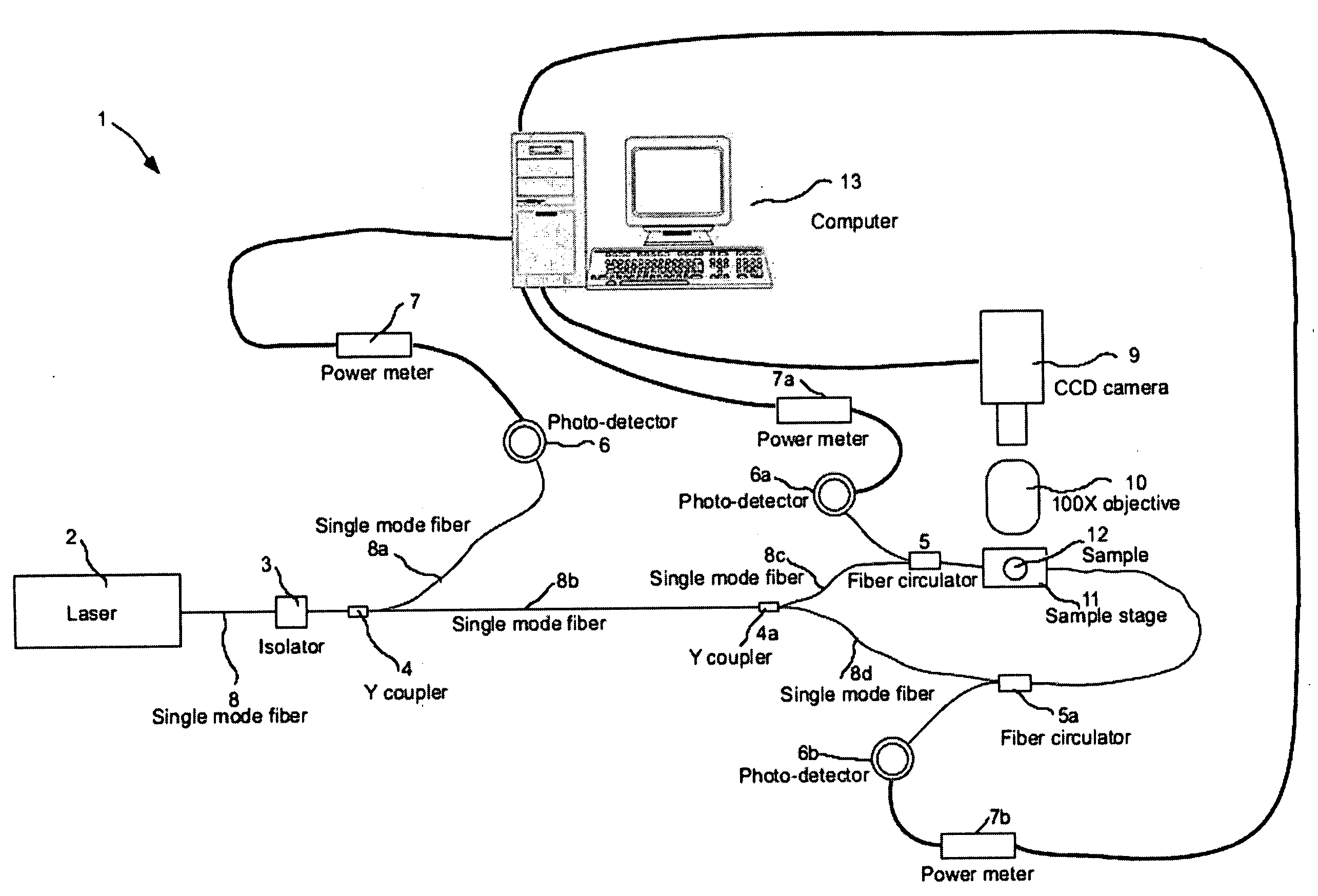
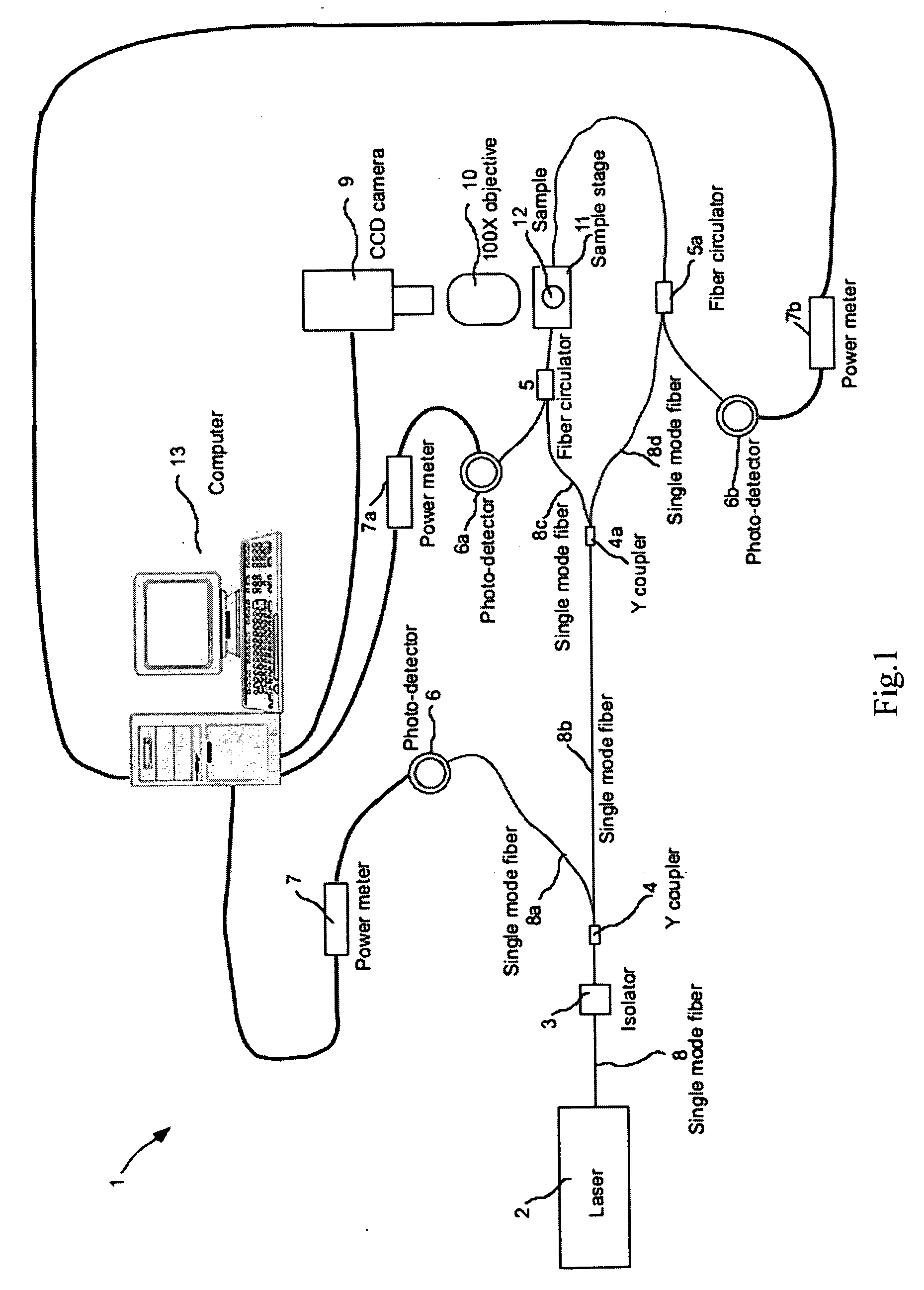
[0022] This example illustrates the operation of the all-fiber double-beam optical trap device 1 as shown in FIG. 1. The laser light with a wavelength of 980 nm generated by a cw semiconductor laser light source 2 enters a single mode fiber 8 connected to the laser light source 2, and then passing through an isolator 3 used to block the laser light reflected from the output side of the isolator 3. Subsequently, the laser light is split into two different single mode fibers 8a and 8b by a Y coupler 4. One of the two single mode fibers 8a transmits 1% of the light to the photo-detector 6 of the power meter 7 to be recorded as reference optical power. The other single mode fiber 8b transmits the remaining 99% light to a Y-coupler 4a to split the light with equal optical power into two single mode fibers 8c and 8d, which are connected to fiber circulators 5 and 5a, respectively, and a sample stage 11 under careful alignment such that the two laser beams emitting from the two single mode...


PUM


Abstract

The present invention provides a method and device for simultaneous optical trapping, stretching, and measurement of morphological deformation of a micro-particle in real-time. Using the setup of the present invention, the deformability of a living cell can be obtained in real-time by measuring the variation in coupling efficiency with optical power of light coupled from one single-mode fiber to the other through the lensing effect of the trapped-and-stretched micro-particle.

Description

BACKGROUND OF THE INVENTION [0001] 1. Field of the Invention [0002] The present invention is related to a method and device for simultaneous trapping, stretching, and real-time measurement of morphological deformation of a particle with extremely high sensitivity. In this invention, the deformability of a particle can be obtained in real-time by measuring the nonlinear coupling efficiency of a laser beam from one single-mode fiber to the other after passing through the micro-particle trapped in a pair of counter-propagating laser beams emitted from the two single-mode fibers. [0003] 2. Description of Related Art [0004] Over the past three decades, it has been found that laser can be utilized to capture and manipulate particles and cells with diameters on the order of a micron to tens of microns. The technologies of laser traps or laser tweezers were developed employing laser light to trap or move micro-particles, which are extremely difficult (if not impossible) to move or manipulat...

Claims


Application Information

Patent Timeline
IPC IPC(8): G01N21/00G01B11/24
CPCG01N15/1475G01N2015/1495G01N2015/1493G01N15/1433
Inventor CHIOU, ARTHURLIN, CHI-HUNGKARMENYAN, ARTASHESHSIAO, I CHING
Owner CHI HUNG LIN
Learn More