Fuel for fuel battery, fuel battery, and power generating method using same
a fuel cell and battery technology, applied in the direction of cell components, electrochemical generators, other chemical processes, etc., can solve the problems of raising the fuel unit price, and achieve the effect of low manufacturing cost, simple manufacturing, and reduced cos
- Summary
- Abstract
- Description
- Claims
- Application Information
AI Technical Summary
Benefits of technology
Problems solved by technology
Method used
Image
Examples
first embodiment
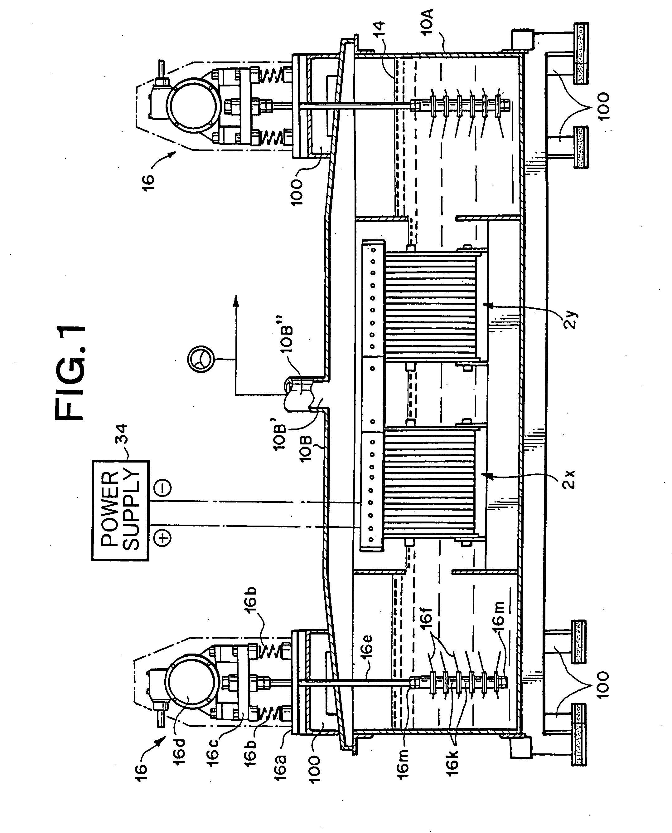
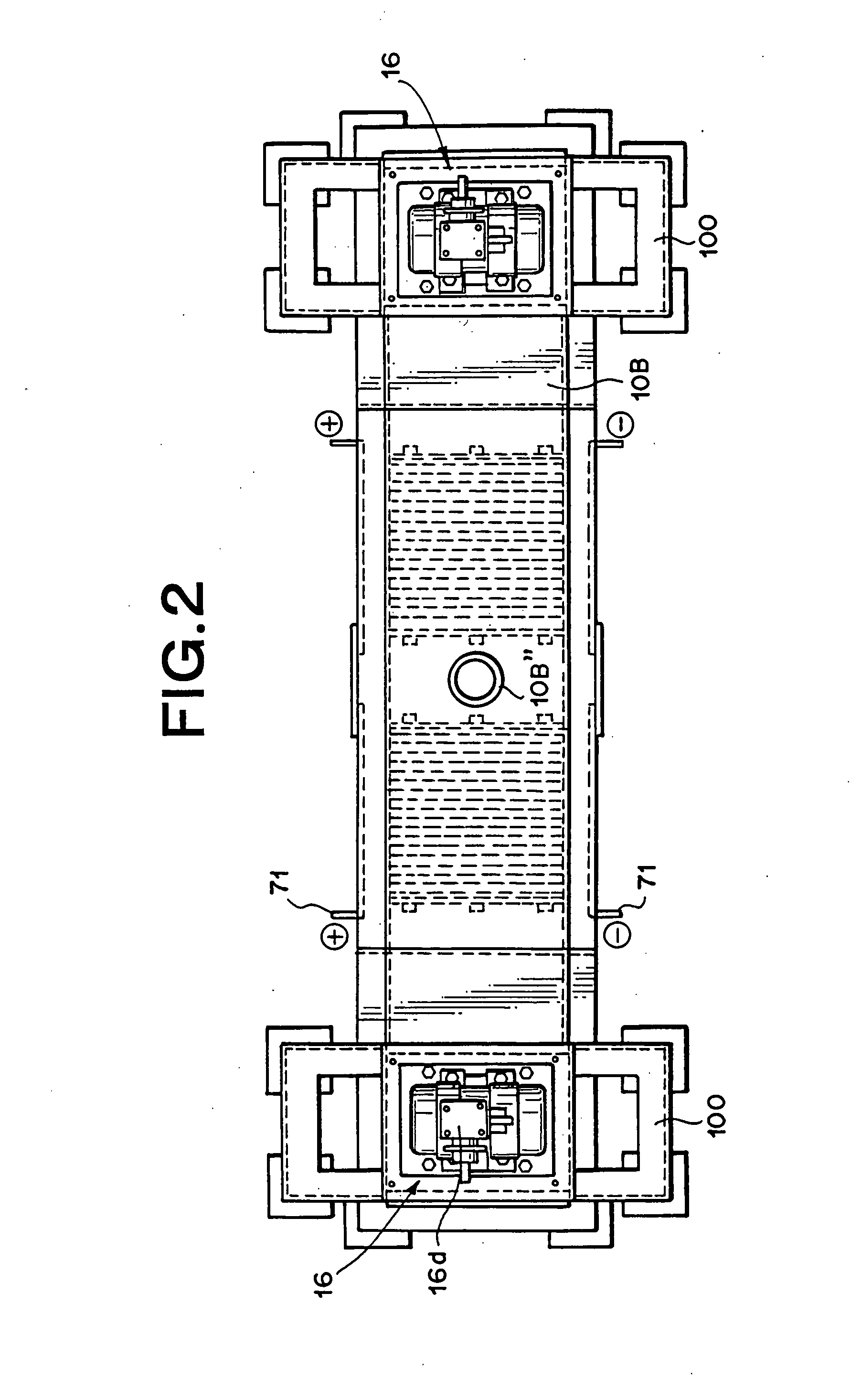
[0325] The hydrogen-based / oxygen-based mixed gas of FIG. 65 through FIG. 67 of the present embodiment utilizes the following.
[0326] (a) Vibro-stirring Means
[0327] Japan Techno Co., Ltd. Product name: Ultravibration Alpha-Agitator Model Alpha-1 (An insulated vibro-stirring means designed so that electrical current flowing in the electrolyte fluid does not flow to the vibration motor.)
[0328] Vibration motor: 75 watt×200 volts×3-phase
[0329] Low-frequency vibration motor made by Murakami Seiki Seisakusho (Corp.)
[0330] Product name: Uras Vibrator
[0331] Vibrating rod: Two rods, 16 millimeters in diameter, SUS304
[0332] Vibrating blade: Four blades, 6 millimeters long, SUS304
[0333] Stationary member: SUS304
[0334] Resilient sheet: Product name: Teflon (Registered trademark) sheet
[0335] (b) Stationary Electrodes [0336] Plus electrode: 27 titanium blades covered with platinum plating [0337] Minus electrode: 24 titanium blades
[0338] (c) Inverter: Fuji Electric (Inc.) Product name FVR...
second embodiment
[0358] The gas generated in the second embodiment was not passed through a safety device and sent directly to a fuel cell as in the first embodiment, rather after storage in a gas accumulator for one day, the hydrogen-based / oxygen-based mixed (raw) gas was directly supplied to the hydrogen gas supply port of the fuel cell of the first embodiment without passing through the seal port of FIG. 59 or the flame stopper tank of FIG. 60. However effects identical to the first embodiment were obtained. Moreover, when the raw gas was analyzed in the same way as previously, nearly the same data and analysis results as for the previous raw gas were obtained. Another point common with the above gas is that is contained about the same the H, H3, HD and OH content.
third embodiment
[0359] In the present embodiment, the hydrogen-based / oxygen-based mixed gas generating means utilizing the vibro-stirring means of FIG. 50 was comprised of the following.
[0360] (a) Vibro-stirring means
[0361] Japan Techno Co., Ltd. Product name: Ultravibration Alpha-Agitator Model Alpha-2
[0362] Vibration motor: 150 watt×200 volts×3-phase
[0363] Vibrating rod: Two rods, 16 millimeters in diameter, SUS304
[0364] Vibrating blade: Five blades, 6 millimeters long, SUS304
[0365] Electrode support blades:
[0366] Minus electrode: 3 sheets, SUS304
[0367] Plus electrode: Two sheets covered with platinum plating, (10 μm thick) SUS304
[0368] (b) Inverter: Fuji Electric (Inc.) Product name FVR-EL11S used after adjusted to 55 Hertz
[0369] (c) Rectifier: Hi-Mini made by Chuo Seisakusho (Corp.)), 200 volts
[0370] (d) Electrolytic tank: Manufactured from (SUS304) stainless steel (inner surface of heat-resistant polyvinyl plastic)
[0371] Inner diameter 220 mm×320 mm×400 mm (H)
[0372] Lid member is ...
PUM
 Abstract
Description
Claims
Application Information
 - R&D
- Intellectual Property
- Life Sciences
- Materials
- Tech Scout
- Unparalleled Data Quality
- Higher Quality Content
- 60% Fewer Hallucinations
Browse by: Latest US Patents, China's latest patents, Technical Efficacy Thesaurus, Application Domain, Technology Topic, Popular Technical Reports.
© 2025 PatSnap. All rights reserved.Legal|Privacy policy|Modern Slavery Act Transparency Statement|Sitemap|About US| Contact US: help@patsnap.com


