Digital servo control unit and laser machining apparatus

a servo control unit and laser machining technology, applied in the direction of electric programme control, program control, instruments, etc., can solve the problems of inability to accurately follow the current command signal, abnormal pulse width modulation of pmw control, and saturated supply voltage of power transistors, so as to reduce the cost of parts of the apparatus and reduce the stability margin of servo control

Inactive Publication Date: 2006-11-30
HITACHI SEIKO LTD
View PDF9 Cites 13 Cited by
  • Summary
  • Abstract
  • Description
  • Claims
  • Application Information

AI Technical Summary

Benefits of technology

[0018] According to the present invention, an analog signal output from the D / A converter is smoothed by the low pass filter or the notch filter so as to be a current command signal. Thus, the current command signal does not have a stepwise waveform synchronizing with a sampling period but has a smooth waveform. Accordingly, a driving current can be controlled to follow the current command signal accurately without occurrence of spike-like pulsation in a current error signal of the current control circuit. The stability margin of servo control can be kept by the stabilizing compensation means for compensating a phase delay caused by the filter. Further, in view of cost, a low-price power supply can be used because the power supply to a power transistor can be made to have a low voltage. The filter can be constituted by a simple operational amplifier circuit, and the stabilizing compensation means can be implemented by a program of the processor. Thus, the cost of parts of the apparatus can be suppressed.

Problems solved by technology

When the pulsation has a high peak value, a power supply voltage to the power transistor may be saturated or the pulse width modulation of the PMW control may be abnormal.
Thus, the driving current cannot be controlled to follow the current command signal accurately.
However, increase of the power supply voltage leads to increase in cost.
However, it is difficult to shorten the sampling period due to the arithmetically processing time of the servo control program.
In addition, even if the sampling period is shortened or the control input signal is interpolated, it will be difficult to suppress the pulsation perfectly when the current command signal changes stepwise.
Thus, there is a fear that the control program may be complicated or the cost of the control unit may increase.

Method used


Image

  • Digital servo control unit and laser machining apparatus
  • Digital servo control unit and laser machining apparatus
  • Digital servo control unit and laser machining apparatus

Examples


first embodiment

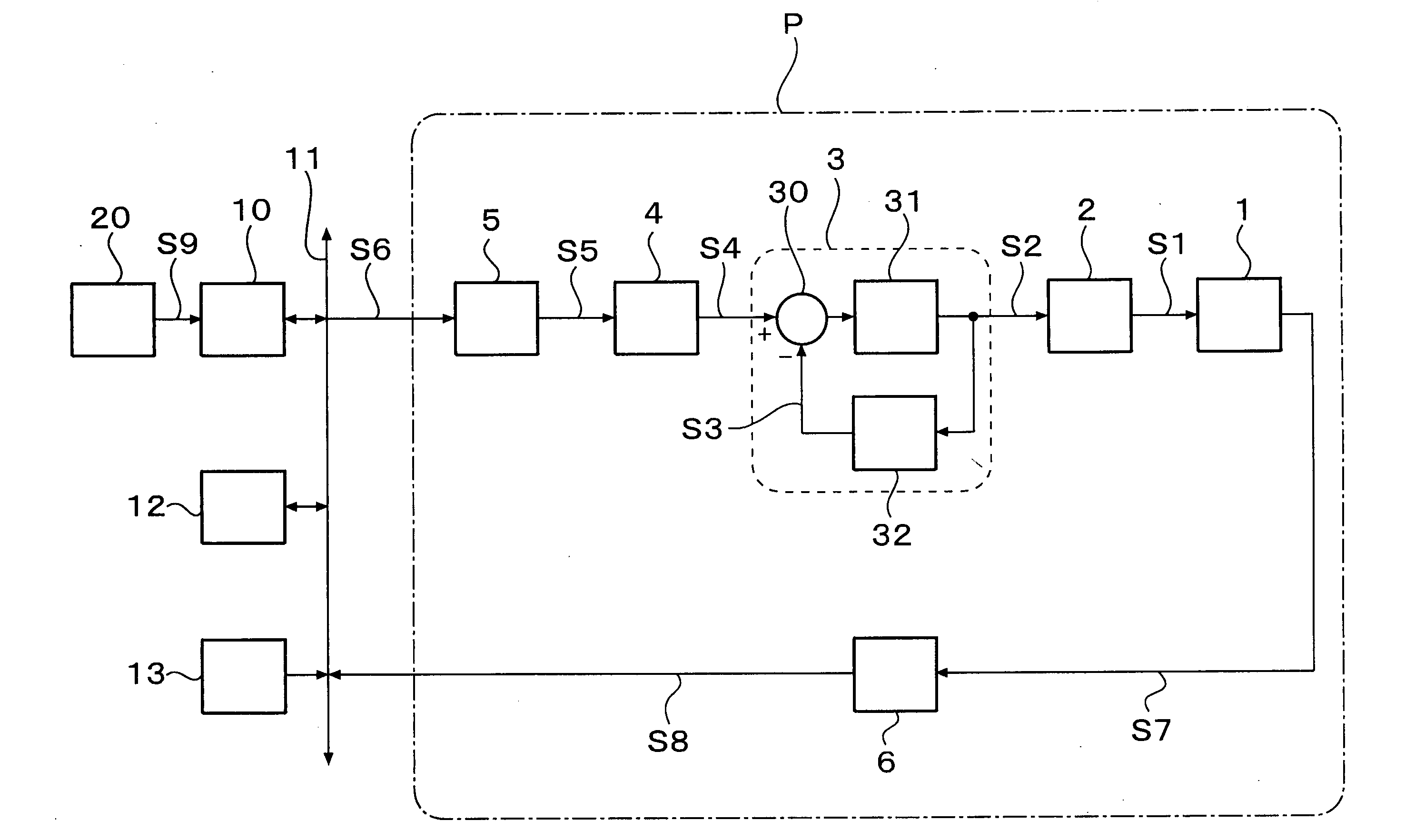
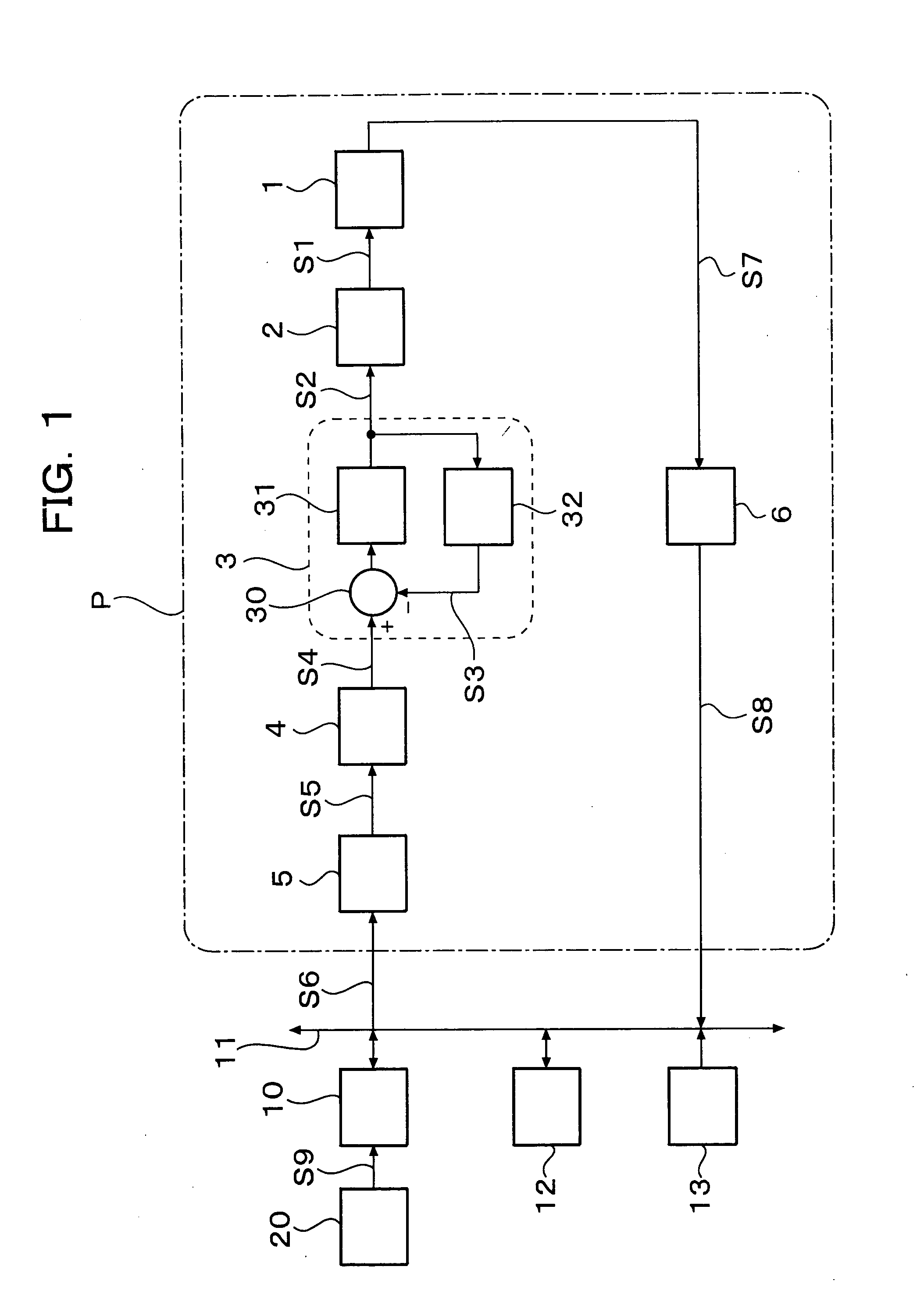
[0030]FIG. 1 is a block diagram of a digital servo control unit according to the present invention.

[0031] This control unit is a unit for digitally controlling the operation of a positioning mechanism 1 by a processor 10. The positioning mechanism 1 is driven by an actuator 2. When the present invention is applied to a digital servo control unit for a steerable mirror, the actuator 2 is a rotary electromagnetic actuator. The steerable mirror is fastened to the rotating shaft of the positioning mechanism 1. The positioning mechanism 1 is a rotor mechanism rotating in accordance with the driving torque generated by the actuator 2.

[0032] The processor 10 is connected to a D / A converter 5, an encoder 6, a random access memory (RAM) 12 and a read only memory (ROM) 13 through a bus 11.

[0033] A host controller 20 transmits an target position signal S9 of positioning operation to the processor 10. The encoder 6 detects a displacement S7 of the positioning mechanism 1 and outputs a discre...

second embodiment

[0070] Although the current command signal S4 is smoothed by the first-order low pass filter 4 in the aforementioned first embodiment, this may be replaced by a second-order low pass filter. Here, when ωLP2 designates a cut-off frequency, ζLP2 designates a damping ratio and kLP2 designates a coefficient deciding a DC gain, a transfer function in the case of a second-order low pass filter is expressed by Expression 13. GLP⁢ ⁢2⁡(s)=kLP⁢ ⁢2s2+2⁢ζLP⁢ ⁢2⁢ωLP⁢ ⁢2⁢s+ωLP⁢ ⁢22(13)

[0071] Though not shown, this second-order low pass filter can be also constituted by a simple operational amplifier circuit. In the same manner as in the first embodiment, the cut-off frequency is set to be lower than the sampling frequency. The configuration of the servo compensator is similar to that of FIG. 5, but the second-order low pass filter has two state variables. Therefore, the state observer 102 estimates the two state variables, and the estimated state variables are multiplied by state feedback coeffi...

third embodiment

[0072] Although the current command signal S4 is smoothed by the low pass filter in the aforementioned first and second embodiments, this may be replaced by a notch filter. Here, when ωN designates a cut-off frequency, ζNd designates a damping ratio of a denominator, and ζNn designates a damping ratio of a numerator, a transfer function in the case of a notch filter is expressed by Expression 14. GN⁡(s)=s2+2⁢ζNn⁢ωN⁢s+ωN2s2+2⁢ζNd⁢ωN⁢s+ωN2(14)

[0073] Though not shown, this notch filter can be also constituted by a simple operational amplifier circuit. In this event, it is intended to suppress spike-like pulsation as shown in FIG. 8B. It is therefore rational to make the cut-off frequency equal to the sampling frequency or an integer multiple of the Nyquist frequency. In order to remove harmonic components of the pulsation, a plurality of notch filters having different cut-off frequencies may be connected in series. Alternatively, a notch filter and a low pass filter may be used togeth...


PUM


Abstract

There is provided a digital servo control unit which uses a D/A converter, which suppresses the spike-like pulsation superimposed on a current error signal inside a current control circuit, and which has control performance not lower than that in the background art even when a low-voltage and low-price power supply circuit is used. The digital servo control unit has a first-order low pass filter acting on an analog signal output by the D/A converter, and a stabilizing compensation means for compensating a phase delay caused by the first-order low pass filter. An output signal of the first-order low pass filter is input to a current control circuit as a current command signal. The first-order low pass filter is formed as a low pass filter having a cut-off frequency which is lower than a sampling frequency. The first-order low pass filter may be replaced by a notch filter having a cut-off frequency which is equal to a sampling frequency or which is equal to an integer multiple of a Nyquist frequency.

Description

FIELD OF THE INVENTION [0001] The present invention relates to a digital servo control unit including a processor for performing a servo control process for every predetermined sampling period, a D / A converter for converting a control input signal calculated by the servo control process, into an analog signal, and a current control circuit for controlling a driving current to be supplied to an actuator in accordance with the D / A-converted control input signal; and a laser machining apparatus for machining while controlling the position of a steerable mirror by means of such a digital servo control unit. DESCRIPTION OF THE BACKGROUND ART [0002] In recent years, mechatronics technologies have been developed conspicuously. For example, sophisticated servo control techniques have been applied to industrial machinery or information equipment so as to realize fast and precise mechanism control, that is, motion control. Particularly digital servo control based on arithmetic processing with...

Claims


Application Information

Patent Timeline
Patent Type & Authority Applications(United States)
IPC IPC(8): G06F19/00G05B13/02H01S3/00H02P29/00
CPCG05B19/21G05B2219/41144G05B2219/45165G05B2219/41232G05B2219/41186
Inventor TOYAMA, SOUICHIOKUBO, YAICHI
Owner HITACHI SEIKO LTD
Why Eureka
Try Eureka