Swing type multidirectional switch device

A multi-directional switch, swing-type technology, applied in electrical switches, electrical components, circuits, etc., can solve the problems of reduced incident light, dim lighting conditions, difficulty in maintaining lighting quality, etc., to improve reliability and reduce component costs.

Active Publication Date: 2014-04-23
ALPS ALPINE CO LTD
View PDF3 Cites 0 Cited by
  • Summary
  • Abstract
  • Description
  • Claims
  • Application Information

AI Technical Summary

Problems solved by technology

[0007] However, in the above-mentioned conventional swing type multi-directional switch device, in the state where each pressing portion of the operation button is illuminated, if the driving body serving as the light guide is rotated (tilted) during operation, the weight of the driving body will be reduced. The bottom surface (incident surface) is inclined relative to the light source, so the amount of incident light from the light source to the driving body is greatly reduced, and each pressing part is in an extremely dim lighting state
That is, in the above-mentioned conventional switch device, the lighting state (brightness) of each pressing portion varies greatly depending on the tilting direction or tilting angle of the operation button, so there is a problem that it is difficult to maintain a good lighting quality during operation.
In addition, it is necessary to make the driving body that rotatably supports the operation button function as a light guide, so there is a problem that the driving body cannot be manufactured at low cost, which will become a major factor that hinders the cost reduction of the device.

Method used


Image

  • Swing type multidirectional switch device
  • Swing type multidirectional switch device
  • Swing type multidirectional switch device

Examples


Embodiment Construction

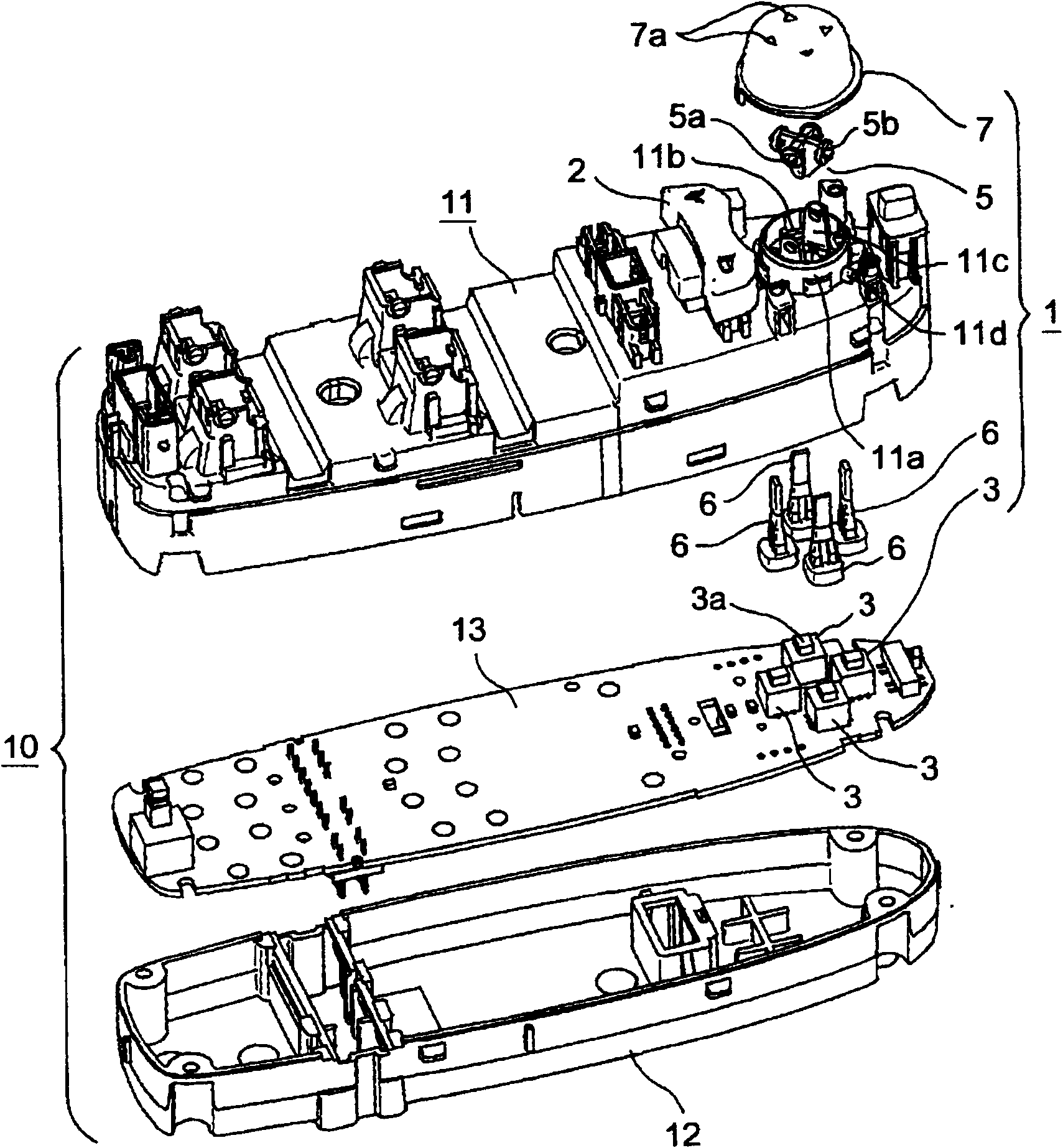
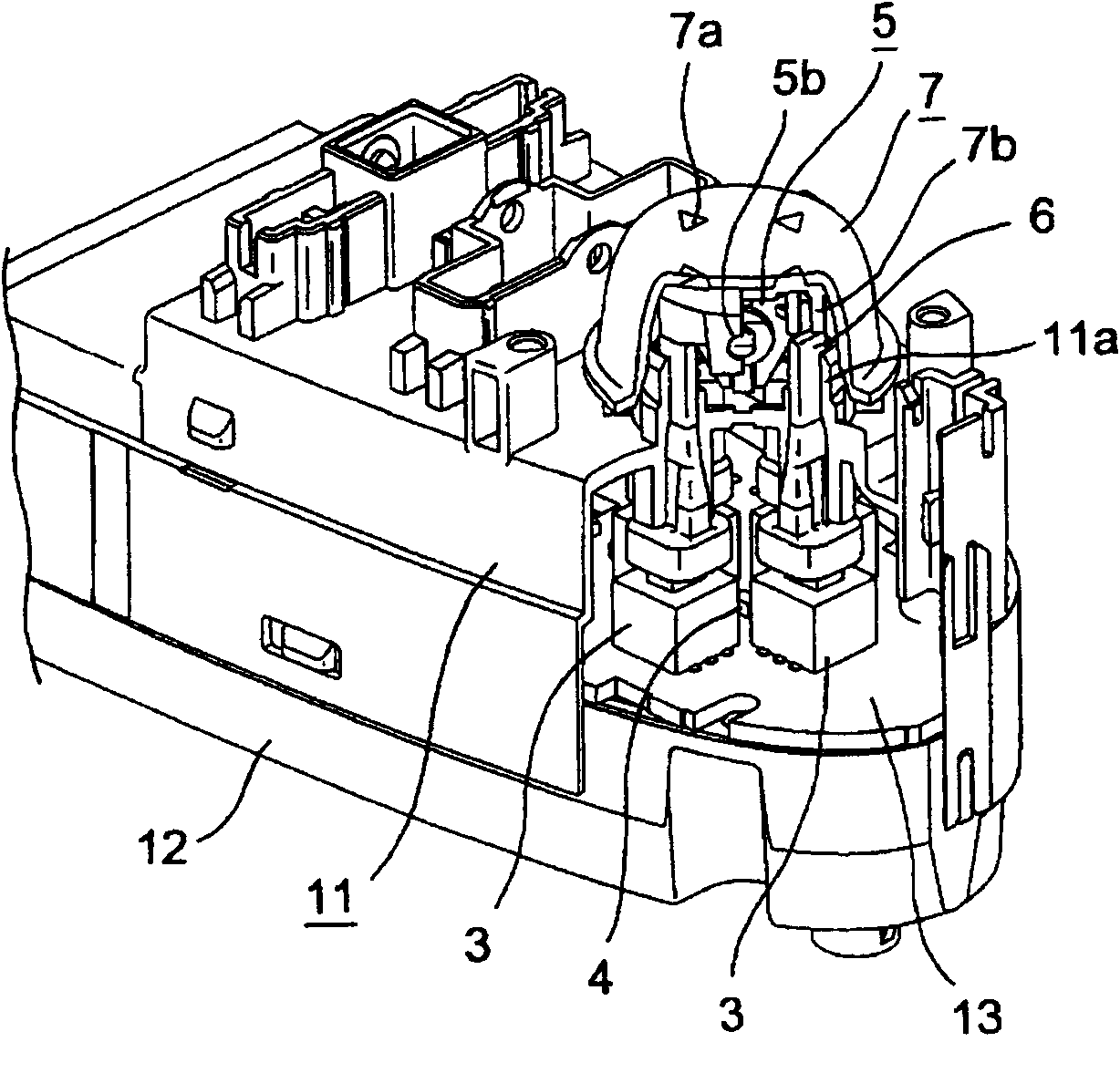
[0044] A swing-type multi-directional switch device 1 according to an embodiment of the present invention will be described. The switch device 1 is incorporated into a Figure 1 ~ Figure 3 The switch unit 10 is shown. This switch unit 10 is arranged on the inboard side of the lateral door of the driver's seat of the motor vehicle. A plurality of switch devices (not shown) for opening and closing windows, etc. It should be noted that the housing of the switch unit 10 includes an upper case 11 covered by a cover not shown and a lower case 12 fixed on the bottom of the upper case 11, and a circuit board 13 placed on the lower case 12 It is accommodated inside the upper case 11 .

[0045] Hereinafter, the swing type multi-directional switch device 1 of the present embodiment will be described with reference to the drawings. The switch device 1 mainly includes: four push button switches 3 and a light source 4 mounted on a circuit board 13; a driving body 5 having a first shaft p...


PUM


Abstract

The invention provides a swing type multidirectional switch device advantaged by good maintenance of lighting quality during operation and easy realization of low cost. The switch device is provided with: a light source and four switch elements received in an upper housing; a drive body making shaft centers of a first shaft part and a second shaft part be perpendicular to each other; actuators respectively mounted on each switch element; an operation button supported by the second shaft part to rotate freely to cover the drive body, wherein, the drive body is supported by the upper house to rotate freely via the first shaft part. The operation button is capable of performing four-direction pressing operations in a 45 degree angle relative to a first straight line and a second straight line, four parts corresponding to each pressing operation direction are provided with pressing parts capable of lighting. The pressing parts are disposed in sections not coincide with each straight line in a top view, therefore, at the back face side of the operation button, light of the light source directly illuminates each pressing part.

Description

technical field [0001] The present invention relates to, for example, a swing-type multi-directional switch device that uses a switch for adjusting the angle of a rearview mirror on a door of a motor vehicle and is provided with pressing parts corresponding to four different pressing operation directions at four positions of the operating button. In particular, it relates to a swing-type multi-directional switch device capable of illuminating each pressing portion with light from a light source. Background technique [0002] As a prior art of such a swing-type multi-directional switch device, Patent Document 1 describes a switch device that includes a support mechanism capable of reliably pressing and operating the operation button in four directions, and facilitates miniaturization of the entire device in plan view. . [0003] In the conventional switch device, the lower part of the driving body serving as the light guide is inserted into the upper opening of the casing fo...

Claims


Application Information

Patent Timeline
Patent Type & Authority Patents(China)
IPC IPC(8): H01H25/00H01H9/18
Inventor 土谷智明
Owner ALPS ALPINE CO LTD
Why Eureka
Try Eureka