Guide structure of optical fiber and wiring method of optical fiber

a technology of optical fiber and guide structure, which is applied in the direction of optical elements, manufacturing tools, instruments, etc., can solve the problems of bending loss, difficult to keep the wiring route of the optical fiber uniform, and excessive bending stress applied, so as to stabilize the wiring route of the optical fiber, reduce the cost of parts, and improve the effect of quality

Inactive Publication Date: 2012-02-09
FUJITSU TELECOM NETWORKS LTD
View PDF1 Cites 2 Cited by
  • Summary
  • Abstract
  • Description
  • Claims
  • Application Information

AI Technical Summary

Benefits of technology

[0011]The present application is made to address to these actual circumstances, and a proposition thereof is to provide a guide structure of an optical fiber and a wiring method of the optical fiber capable of keeping a wiring route of the optical fiber uniform and enabling suppression of a parts cost.
[0019]According to the guide structure of the optical fiber of the above-stated embodiments, the uniformity and the stabilization of the wiring route of the optical fiber are enabled by the guide wired by the guide pins at the time of wiring the optical fiber, and therefore, the quality is stabilized.
[0020]Besides, the guide pins pulled out of the guide pin mounting holes after the wiring are reusable, and therefore, there is an advantage that parts cost is reduced compared to a conventional guide structure in which fiber guides are mounted by each product.
[0021]The lift preventing unit provided at the guide pin prevents the lifting of the optical fiber at the time of wiring the optical fiber, and therefore, there is an advantage of high workability. Also, by making the lifting preventing unit be the concave portion, there is an advantage in which an attachment / detachment operation of the guide pin is easy because it is possible to insert the guide pin into the guide pin mounting hole regardless of top and bottom of the guide pin, and further, the projection functions as the grip portion of the guide pin by providing the projection at the upper portion of the guide pin.
[0022]On the other hand, according to the wiring method of the optical fiber of the above-stated embodiments, it is possible to form the guide at the case and the printed circuit board by the simple work of attaching / detaching the guide pins to / from the guide pin mounting holes formed at the case and the printed circuit board. As a result, there is an advantage in which the uniformity and the stabilization of the wiring route of the optical fiber are enabled by the guide at the time of wiring the optical fiber.
[0023]In addition, it is possible to enable the uniformity and the stabilization of the wiring route for any number of times by using the reusable guide pins and further, there is an advantage of high workability because the lift preventing unit provided at the guide pin prevents the lifting of the optical fiber at the time of wiring the optical fiber.

Problems solved by technology

Incidentally, the optical fiber is made of a quartz glass, and therefore, it is fractured when excessive bending stress is applied.
Besides, light passing inside the optical fiber goes straight, and therefore, bending loss occurs when more than a predetermined bending is applied to incur deterioration of light amount and there is a case when product characteristics are not satisfied.
However, an actual circumstance is that it is difficult to keep the wiring route of the optical fiber uniform resulting from variation in operations.
However, there have been defects in which the fiber guides have to be designed and manufactured by each product because the wiring routes of the optical fiber are different by each component and product type to be mounted, in addition, a cost for fiber guide members is further required as a parts cost of the product because the fiber guide is mounted at the product, if the fiber guide is provided at the wiring route as stated above.
Similarly, there also is a problem in a conventional example disclosed in Japanese Utility Model Application Publication No, H07-3228 in which a cost for the electric wire holder is necessary as the parts cost of the product because the electric wire holders are inserted and fixed to the base plate.

Method used


Image

  • Guide structure of optical fiber and wiring method of optical fiber
  • Guide structure of optical fiber and wiring method of optical fiber
  • Guide structure of optical fiber and wiring method of optical fiber

Examples


Embodiment Construction

[0040]Hereinafter, embodiments of the present invention are described in detail based on the drawings.

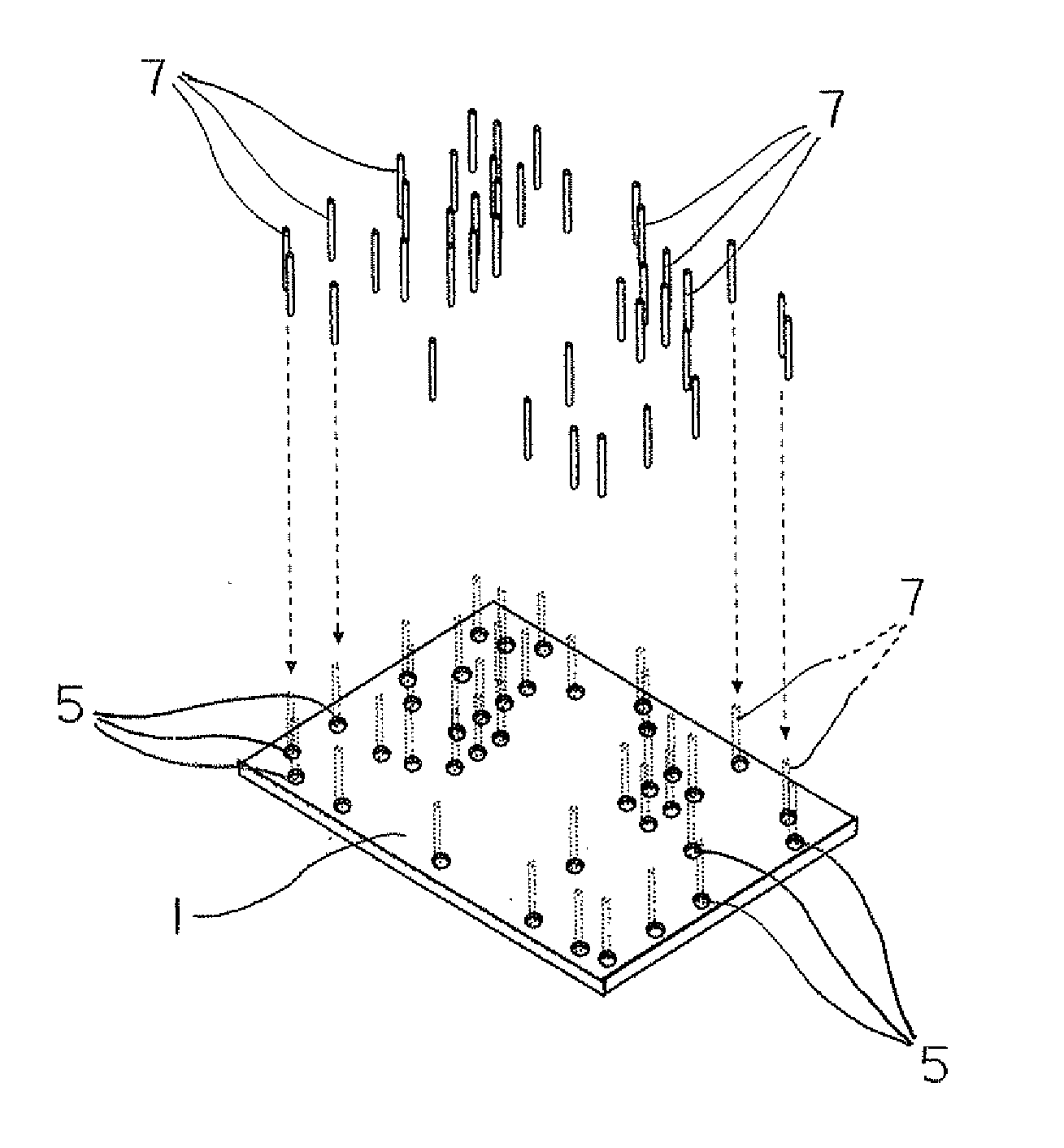
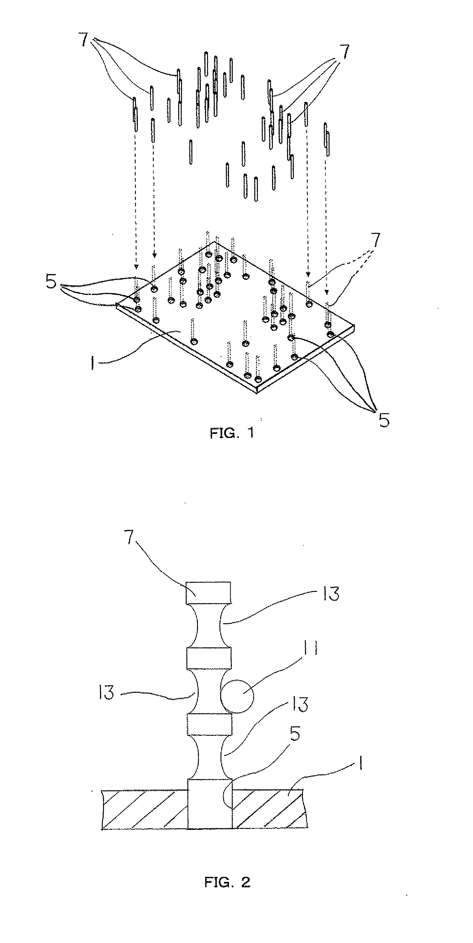
[0041]FIG. 1 to FIG. 6 represent a guide structure of an optical fiber according to one embodiment of the present invention. In FIG. 1, a reference numeral 1 is a case (lower case) in a rectangular state when seen from above to which optical parts 3 such as a laser diode illustrated in FIG. 4 are mounted, and a number of guide pin mounting holes 5 in a circular state when seen from above are provided at the case 1 in accordance with a wiring route R of an optical fiber illustrated in FIG. 5, to mount the optical parts 3.

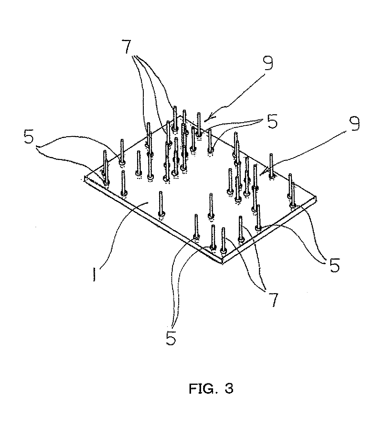
[0042]Besides, reference numerals 7 are guide pins each in a circular shape in cross section which are attachable / detachable to / from each of the guide pin mounting holes 5 in FIG. 1. A guide 9 in which wiring of the optical fiber is performed along the wiring route R is formed on the case 1 by each of the guide pins 7 when the guide pins 7 are inserted into each of t...


PUM

PropertyMeasurementUnit
conductiveaaaaaaaaaa
guide structureaaaaaaaaaa
bending stressaaaaaaaaaa

Abstract

A guide structure of an optical fiber includes a case in which a plurality of guide pin mounting holes are provided in accordance with the wiring route of the optical fiber, a plurality of guide pins formed of a conductive material, detachably attached to each of the guide pin mounting holes, and pulled out of each of the guide pin mounting holes after wiring the optical fiber, and providing a guide for wiring the optical fiber at the case by inserting each of the guide pins into each of the guide pin mounting holes.

Description

CROSS REFERENCE TO RELATED APPLICATION[0001]This application is based upon and claims the benefit of priority from Japanese Patent Application No. 2010-176270, filed on Aug. 5, 2010, the entire contents of which are incorporated herein by reference.BACKGROUND[0002]1. Field[0003]The present application relates to a guide structure of an optical fiber and a wiring method of the optical fiber keeping a wiring route of the optical fiber uniform.[0004]2. Description of the Related Art[0005]A lot of optical parts are mounted inside an optical communication apparatus and an optical module, and various functions are enabled by coupling these optical parts with an optical fiber and wiring an optical circuit inside an apparatus or a product. Accordingly, a lot of optical fibers are wired inside the optical communication apparatus and the optical module.[0006]Incidentally, the optical fiber is made of a quartz glass, and therefore, it is fractured when excessive bending stress is applied. Besi...

Claims


Application Information

Patent Timeline
Patent Type & Authority Applications(United States)
IPC IPC(8): G02B6/00B23P11/00
CPCG02B6/3612Y10T29/49826G02B6/43
Inventor HORIE, NOBUYUKI
Owner FUJITSU TELECOM NETWORKS LTD
Why Eureka
Try Eureka