
Wizard for configuring a motor drive system

a technology of motor drive and wizard, which is applied in the direction of program control, dynamo-electric converter control, instruments, etc., can solve the problems of inability to achieve and maintain synchronicity between printing stations, inability to achieve and maintain synchronicity, and excessive flaws in product generated products

Active Publication Date: 2006-11-30
ROCKWELL AUTOMATION TECH
View PDF8 Cites 14 Cited by
  • Summary
  • Abstract
  • Description
  • Claims
  • Application Information

AI Technical Summary

Benefits of technology

[0014] The present inventors have recognized that a wizard may be employed to gather information about the partic...

Problems solved by technology

A lack of synchronicity between the stations results in misregistration between the colors, leading to unacceptable product that may need to be scrapped.
In a mechanical line shaft system, factors such as play in the mechanical linkages, stretching of the paper web, and torsional flexing of the line shaft itself make it difficult to achieve and maintain synchronicity between the printing stations, especially during periods of acceleration and deceleration of the printing system.
It has been observed that when synchronicity is not maintained, product generated includes excessive flaws and is often unacceptable for intended use.
Mechanical line shafts also have reduced flexibility in addressing print changes.
Hence, where changes are required, down time may be excessive.
Lack of synchronicity in an electronic line shaft results in similar problems, such as color misregistration, evident in a mechanical line shaft system.
For instance, motor inertia between motors at different stations is often non-uniform and can cause one motor to drift from the other motors.
However, higher control bandwidth does not necessarily equate to higher performance.
To this end, as control bandwidth increases, so does the susceptibility of a motor drive to noise which can lead to operation, rattles, clunks, tendency to resonate, lack of robust performance, etc.
In fact, in many cases, the noise level that results from operating a drive at a maximum bandwidth associated with high CPU clock cycles, instead of increasing control performance has been known to degrade performance appreciably.
The effective selection of control parameters (e.g., gain constants, filter coefficients, compensation techniques) typically requires time-consuming, iterative tuning by highly skilled motor control technicians.
Hence, the process of configuring a motor control system is expensive, and the results may vary depending on the skills and experience of the particular individual performing the configuration.

Method used


Image

  • Wizard for configuring a motor drive system
  • Wizard for configuring a motor drive system
  • Wizard for configuring a motor drive system

Examples


Embodiment Construction

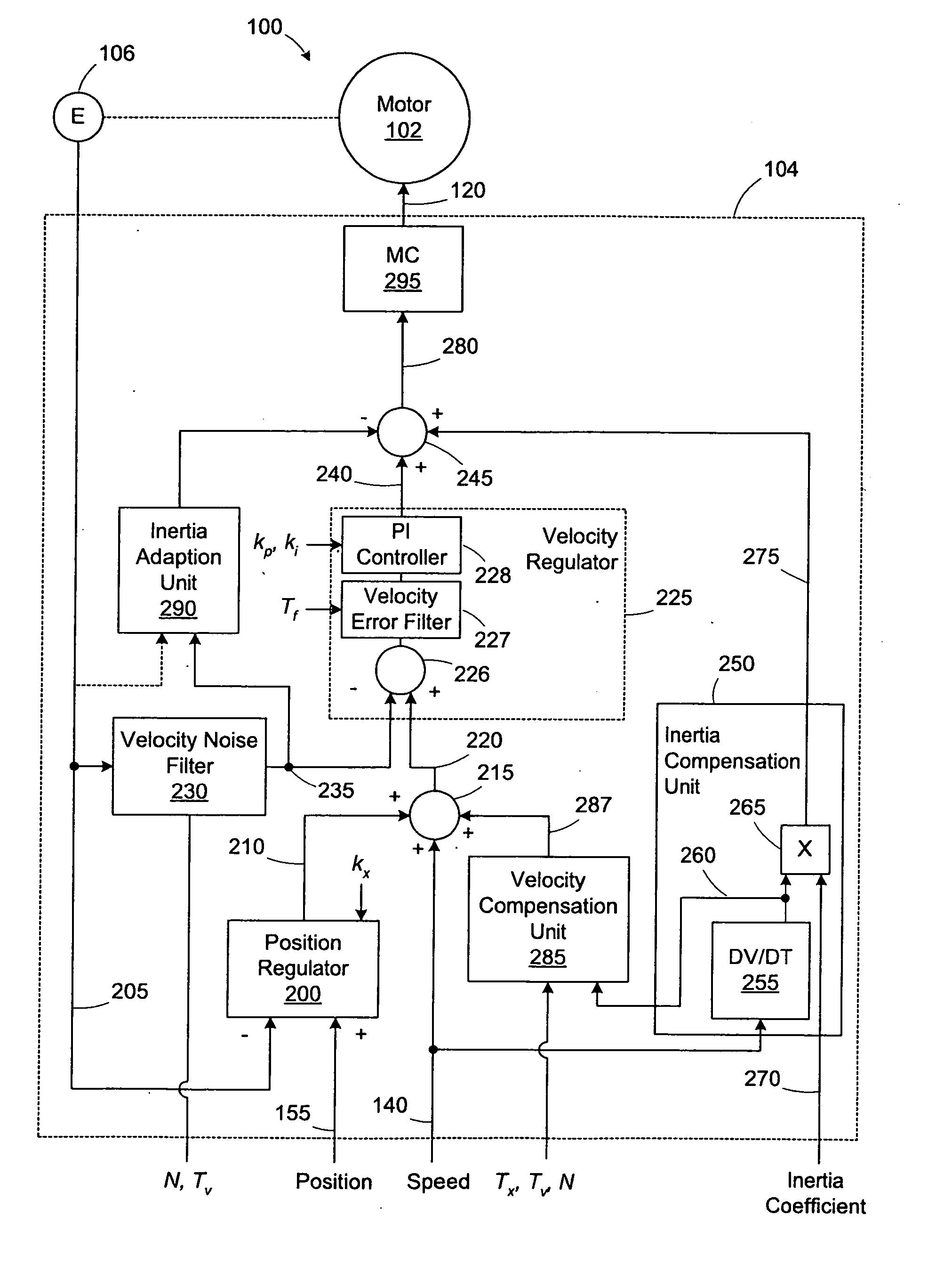
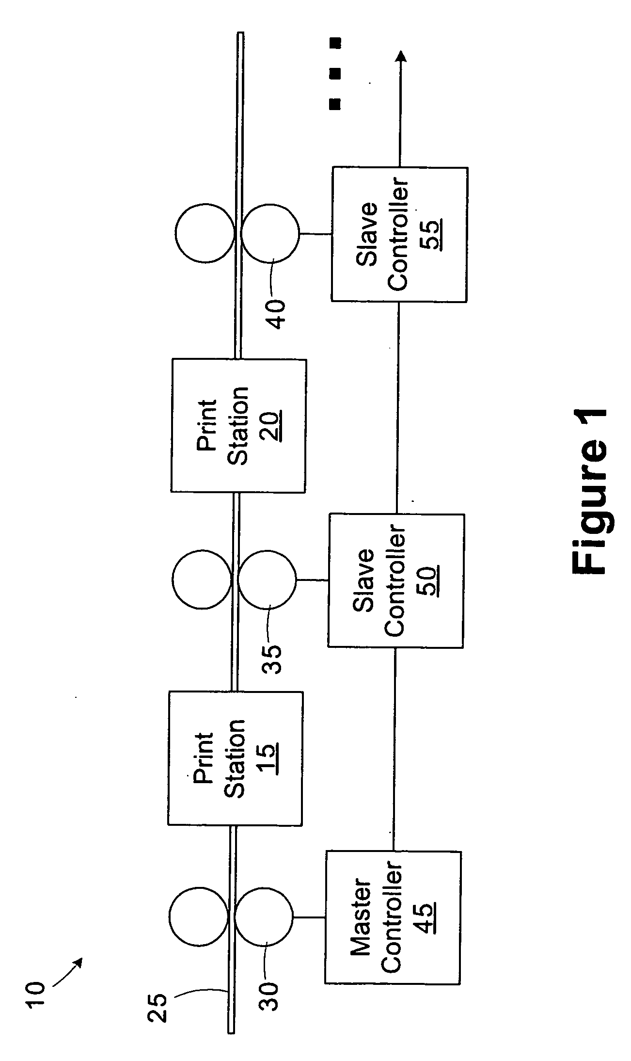
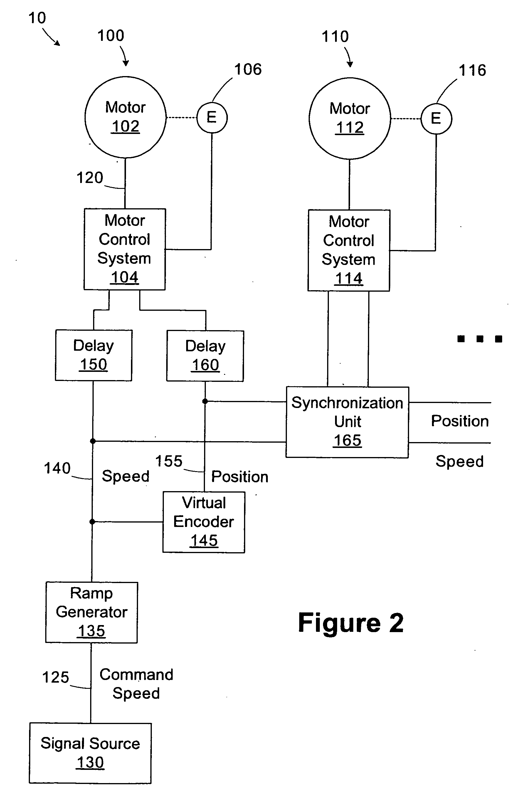
[0030] One or more specific embodiments of the present invention will be described below. It is specifically intended that the present invention not be limited to the embodiments and illustrations contained herein, but include modified forms of those embodiments including portions of the embodiments and combinations of elements of different embodiments as come within the scope of the following claims. It should be appreciated that in the development of any such actual implementation, as in any engineering or design project, numerous implementation-specific decisions must be made to achieve the developers' specific goals, such as compliance with system-related and business related constraints, which may vary from one implementation to another. Moreover, it should be appreciated that such a development effort might be complex and time consuming, but would nevertheless be a routine undertaking of design, fabrication, and manufacture for those of ordinary skill having the benefit of thi...


PUM


Abstract

An electronic line shaft includes a motor drive and a processing unit operable to execute a wizard for configuring the motor drive. The wizard is operable to receive mechanical characteristic data associated with the motor drive, determine a noise parameter based on the mechanical characteristic data, and determine at least one control parameter of the motor drive based on the noise parameter.

Description

CROSS-REFERENCE TO RELATED APPLICATIONS [0001] Not applicable. STATEMENT REGARDING FEDERALLY SPONSORED RESEARCH OR DEVELOPMENT [0002] Not applicable BACKGROUND OF THE INVENTION [0003] The present invention relates generally to motor control and, more particularly, to a wizard for configuring a motor drive system. [0004] This section of this document is intended to introduce various aspects of art that may be related to various aspects of the present invention described and / or claimed below. This section provides background information to facilitate a better understanding of the various aspects of the present invention. It should be understood that the statements in this section of this document are to be read in this light, and not as admissions of prior art. [0005] Rotating motors are typically controlled by a motor drive that receives a reference motor velocity signal and, based on the motor velocity signal, produces and outputs a torque signal that is applied to the motor. Adjust...

Claims


Application Information

Patent Timeline
IPC IPC(8): G05D23/275
CPCG05B19/409G05B2219/33114G05B2219/45187G05B2219/36122G05B2219/33127
Inventor BAUMANN, KEVIN L.REHM, THOMAS J.PIEFER, RICHARD W.GOLOWNIA, JOHN JOSEPH JR.KELLER, JOHN M.STRINGFELLOW, DAVID CHRISTOPHERKELLER, MICHAEL ROBERT
Owner ROCKWELL AUTOMATION TECH
Learn More