
Corneal mask formed of degradation resistant polymer and providing reduced corneal deposits

a degradation-resistant polymer and corneal mask technology, applied in the field of corneal inlay devices, can solve the problems of inability to adapt to the individual, inability to see up close without vision correction, and no such device is currently on the mark

Inactive Publication Date: 2006-11-23
ACUFOCUS
View PDF99 Cites 125 Cited by
  • Summary
  • Abstract
  • Description
  • Claims
  • Application Information

AI Technical Summary

Benefits of technology

[0247] The various methods and techniques described above provide a number of ways to carry out the invention. Of course, it is to be understood that not necessarily all objectives or advantages described may be achieved in accordance with any particular embodiment described herein. Thus, for example, those skilled in the art will recognize that the devices may be made that achieve or optimize one advantage or group of advantages as taught herein without necessarily achieving other objectives or advantages as may be taught or suggested herein.

Problems solved by technology

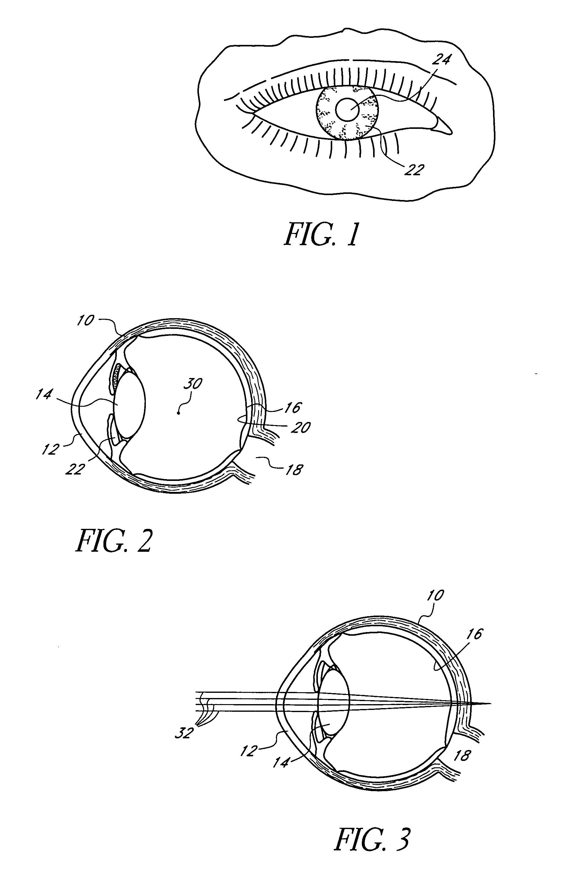
As some individuals age, the ability to accommodate diminishes and these individuals cannot see up close without vision correction.
While this approach is sometimes satisfactory, some have proposed implanting devices inside the eye to improve accommodation for older patients.
While this type of device has been discussed in various contexts, and a need for the device has been identified, no such device is currently on the market.
Several factors make a successful device of this type elusive.
In particular, the device needs to improve the depth of field of a patient's vision and, because it is surgically implanted, the device has to have a very long life-span.
No known device has been proposed that has an adequate life-span.
Copolymerization reduces extractability, a problem with many stabilizers that are merely physically combined with a polymer.

Method used


Image

  • Corneal mask formed of degradation resistant polymer and providing reduced corneal deposits
  • Corneal mask formed of degradation resistant polymer and providing reduced corneal deposits
  • Corneal mask formed of degradation resistant polymer and providing reduced corneal deposits

Examples


Embodiment Construction

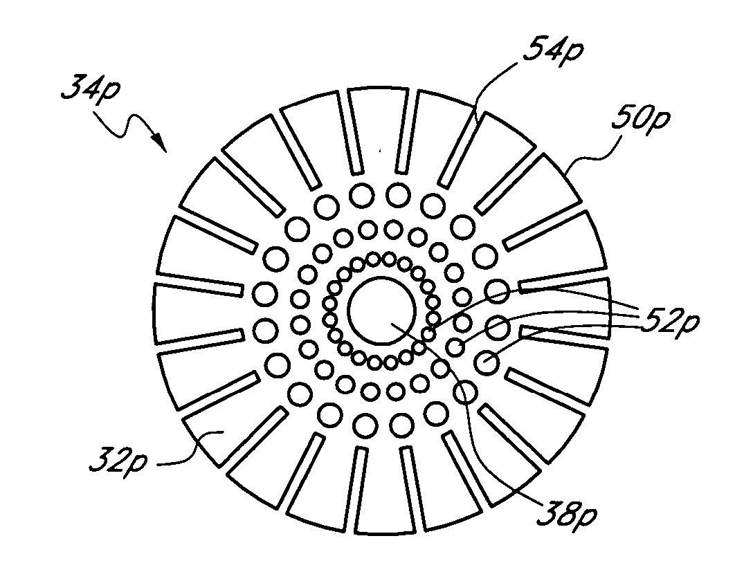
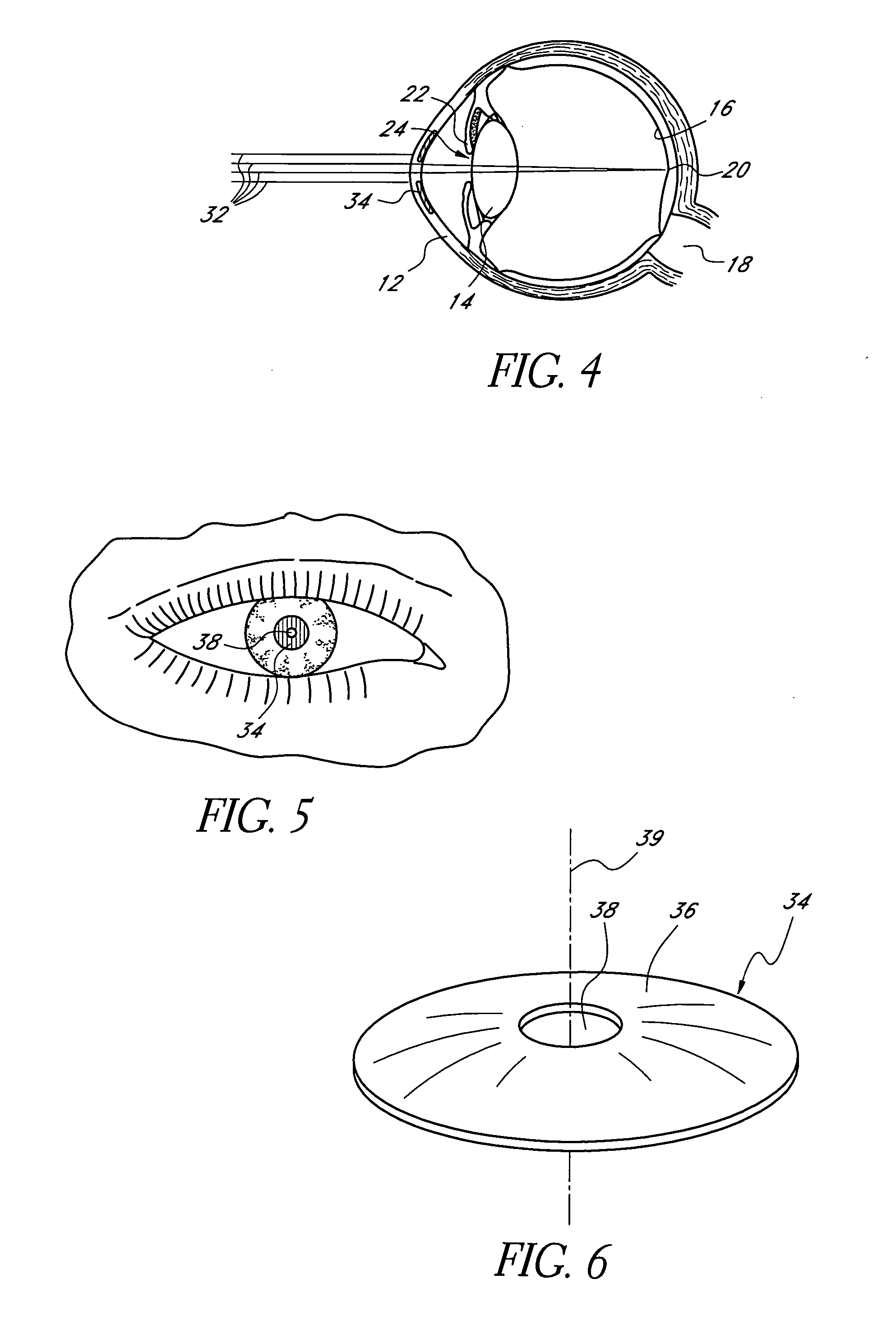
[0080] This application is directed to masks for improving the depth of focus of an eye of a patient and methods and apparatuses for making such masks. The masks generally employ pin-hole vision correction and have nutrient transport structures in some embodiments. The masks may be applied to the eye in any manner and in any location, e.g., as an implant in the cornea (sometimes referred to as a “corneal inlay”). The masks can also be embodied in or combined with lenses and applied in other regions of the eye, e.g., as or in combination with contact lenses or intraocular lenses. In some applications, discussed further below, the masks are formed of a stable material, e.g., one that can be implanted permanently.

I. Overview of Pin-Hole Vision Correction

[0081] As discussed above, mask that has a pinhole aperture may be used to improve the depth of focus of a human eye. As discussed above, presbyopia is a problem of the human eye that commonly occurs in older human adults wherein the...


PUM

PropertyMeasurementUnit
thicknessaaaaaaaaaa
thicknessaaaaaaaaaa
thickaaaaaaaaaa

Abstract

Disclosed are masks configured to be implanted in a cornea of a patient. In one embodiment, the body of the mask has a light transmitting portion, a light blocking portion disposed about the light transmitting portion, and an outer periphery surrounding the light blocking portion. The mask is adapted to reside between two intracorneal layers of a cornea. In a preferred embodiment, the mask is formed from a material comprising a highly fluorinated polymeric material and an opacification agent and is resistant to degradation upon exposure to ultraviolet light. In another embodiment, the mask is formed from a material which comprises a polyanionic compound. In some embodiments, the mask includes one or more wound healing modulator compounds to aid in proper healing following implantation.

Description

RELATED APPLICATION INFORMATION [0001] This application is a continuation-in-part of U.S. patent application Ser. No. 11 / 106,043, filed Apr. 14, 2005, the disclosure of which is hereby incorporated by reference in its entirety.BACKGROUND OF THE INVENTION [0002] 1. Field of the Invention [0003] This application is related to corneal inlay devices. More particularly, this application is directed to corneal inlays that are configured not to degrade over the useful life of the inlay, and that can include one or more compounds to aid in proper healing following implantation and / or include one or more materials which reduce the amount of corneal deposits formed thereon as compared to a mask without such material. [0004] 2. Description of the Related Art [0005] A normally functioning human eye is capable of selectively focusing on either near or far objects through a process known as accommodation. Accommodation is achieved by inducing deformation in a lens located inside the eye, which is...

Claims


Application Information

Patent Timeline
Patent Type & Authority Applications(United States)
IPC IPC(8): A61F2/14A61F2/16G02C7/16
CPCA61F2/14A61F9/0008A61F9/00834A61L27/16A61L2430/16G02C7/165G02C7/04C08L27/16A61F2/15G02C7/02A61F2/145
Inventor SILVESTRINI, THOMAS A.
Owner ACUFOCUS
Learn More