
Device for combination of light of different wavelengths

a technology of light and wavelength, applied in the field of devices for combining light of different wavelengths, can solve the problem of deciding whether to call this filter edge filter, etc., and achieve the effect of cost-effective production

Active Publication Date: 2006-11-16
OERLIKON SURFACE SOLUTIONS AG PFAFFIKON
View PDF3 Cites 10 Cited by
  • Summary
  • Abstract
  • Description
  • Claims
  • Application Information

AI Technical Summary

Benefits of technology

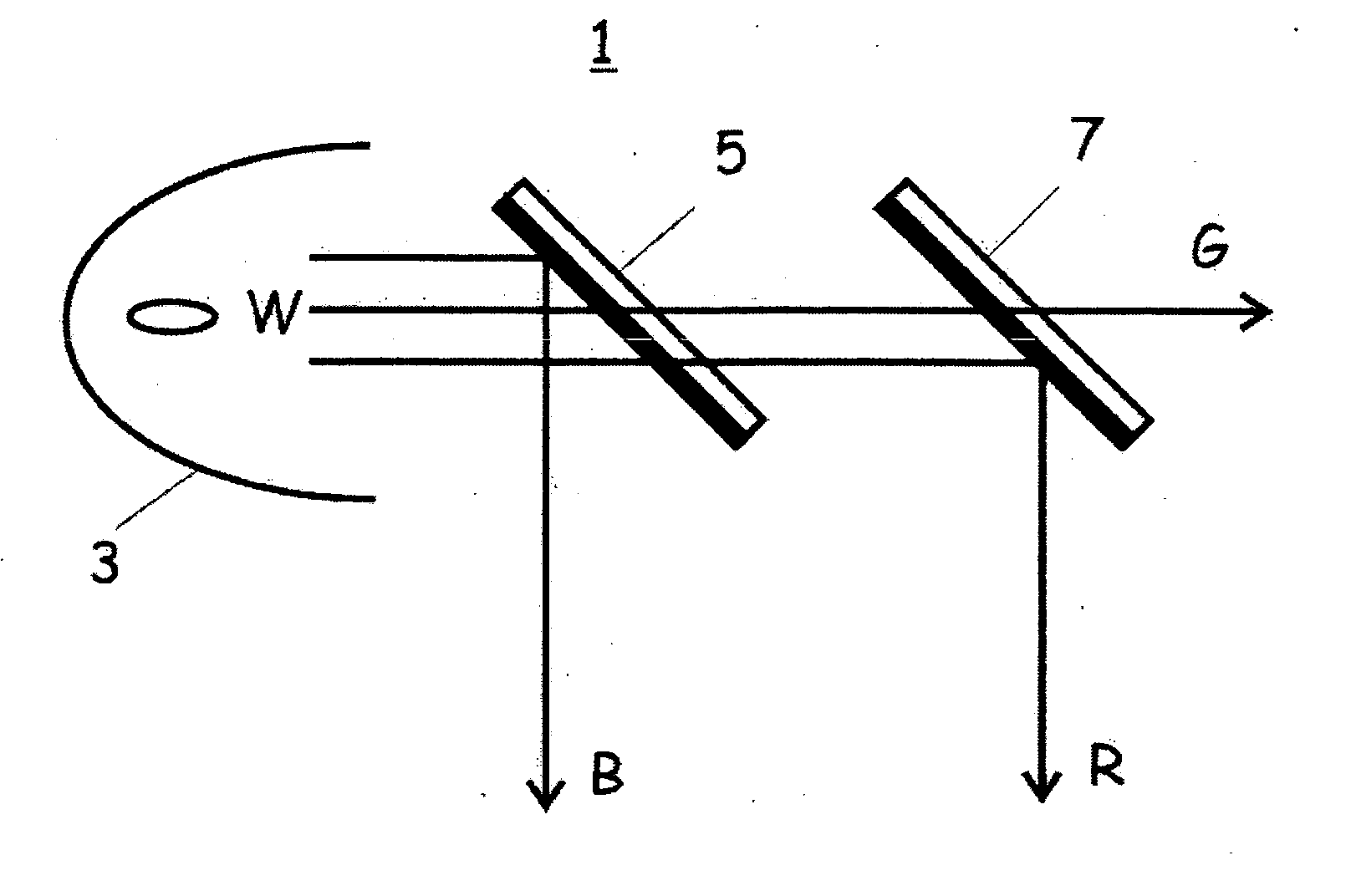
[0015] In contrast, no polarization-selective element is utilized in illumination configurations for imaging elements in which the polarization does not play a role. According to the present invention rather a so-called green bandpass filter is required and utilized. Such a filter can, for example, be realized thereby where on one side of a substrate, a shortpass filter is applied with the position of the edge at approximately 600 nm, while on the other side a longpass filter is applied with the position of the edge at approximately 500 nm. In this way, blue light is reflected on the side with the longpass filter and red light is reflected on the side with the shortpass filter. Only green light is transmitted through both sides of the substrate. This permits the efficient combining and / or splitting of the green light with or from light components which include red as well as also blue light. As already described above, it is advantageous here that the additional filter can be an RB splitter. In the green wavelength range, which forms the transition between the red wavelength range and the blue wavelength range, there are no specifications which have to be satisfied and therefore effects, such as polarization shift or angle shifts, do not play any role or at least they play only a subordinate one.
[0016] In an especially preferred embodiment of the present invention, the bandpass filter, however, is not realized as a two-sided one, but rather in a novel way is applied on one side of the substrate, i.e. on one side of the substrate, the bandpass filter is realized by means of a layer system. On the other side, if it is considered necessary, only an antireflection coating is provided comprising a few layers. Such single-side bandpass filters are generally considered to be difficult to produce. However, novel and substantially statistical design methods simplify this task considerably. It has unexpectedly been found that such a single-sided design with only 60% of the total thickness of a comparable two-sided design can be produced with substantially lower coating complexity and therefore much more cost-effectively.

Problems solved by technology

It is therefore even questionable whether this filter should be called an edge filter in the sense of the above provided definition.

Method used


Image

  • Device for combination of light of different wavelengths
  • Device for combination of light of different wavelengths
  • Device for combination of light of different wavelengths

Examples


Embodiment Construction

[0048] The invention will be explained as follows in further detail by example and in conjunction with the figures.

[0049]FIG. 1a illustrates schematically the condition according to the prior art in the case of a white light source. In the illumination configuration 1 of FIG. 1a, a white light source is shown, which radiates white light W. A longpass filter 5 is placed downstream in the light path at an angle of 45° with the filter edge at approximately 500 nm for the reflection of blue light B and transmission of green light G and red light R. A shortpass filter 7 is placed further downstream into the light path at an orientation of 45° with edge position at approximately 600 nm, which transmits green light G and reflects red light R.

[0050]FIG. 1b depicts schematically an illumination configuration 10 according to the prior art with respect to narrowband light sources to be combined. The blue LED 11, the red LED 13 and the green LED 15 are shown, whose light is combined by means ...


PUM


Abstract

The present invention relates to a method for combining or for splitting the beam paths of substantially nonpolarized light of at least three different wavelength intervals. The splitting or the combining of the beam path of light of those wavelength intervals located between the other wavelength intervals takes place when the beam paths of the light of the two other wavelength intervals are already or still combined. The present invention also relates to an illumination unit comprising a white light source and utilizing this method by means of interference filters for splitting the white light into red, blue and green light beams. The invention also relates to an illumination unit comprising a red, green and blue light source and utilizing these methods by means of interference filters for the combination of the beam paths of the light sources.

Description

TECHNICAL FIELD [0001] The present invention relates to a device for combining light of different wavelengths. The invention relates in particular to an illumination unit with the capability of combining light from red, green and blue narrowband light sources into white light. However, the invention also relates to an illumination unit with the capability of splitting white light into red, green and blue subbeams. PRIOR ART [0002] Projectors currently in use which build on the projection of light for image generation can essentially be divided into 2 categories: those which provide for each of the three color channels red (R), green (G) and blue (B) with one imaging element each (3P Projectors=3 Panel Projectors). To the red color channel is assigned light with wavelengths within the wavelength interval of 600 nm to 780 nm. To the green color channel is assigned light with wavelengths within the wavelength interval of 500 nm to 600 nm. To the blue color channel is assigned light wit...

Claims


Application Information

Patent Timeline
IPC IPC(8): G02B27/14
CPCG02B27/102G02B27/145G02B27/142G02B27/1033
Inventor ZUEGER, OTHMAR
Owner OERLIKON SURFACE SOLUTIONS AG PFAFFIKON
Learn More