
Apparatus and method for measuring while drilling

a technology for measuring equipment and drilling holes, applied in the direction of surveying, directional drilling, borehole/well accessories, etc., can solve the problems of increasing the wear on the drill string and the casing, increasing the cost of drilling, so as to improve the cost efficiency and drilling performance.

Inactive Publication Date: 2006-11-16
SCHLUMBERGER TECH CORP
View PDF44 Cites 58 Cited by
  • Summary
  • Abstract
  • Description
  • Claims
  • Application Information

AI Technical Summary

Benefits of technology

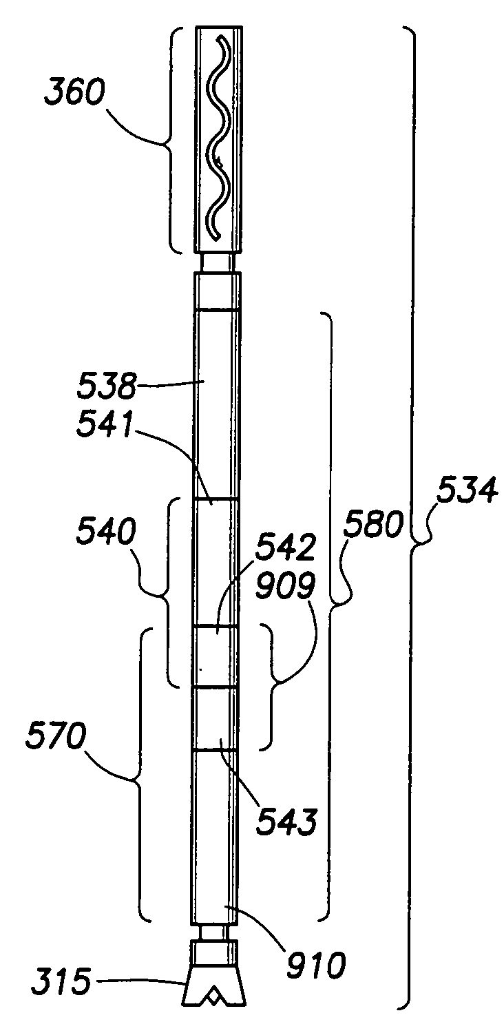
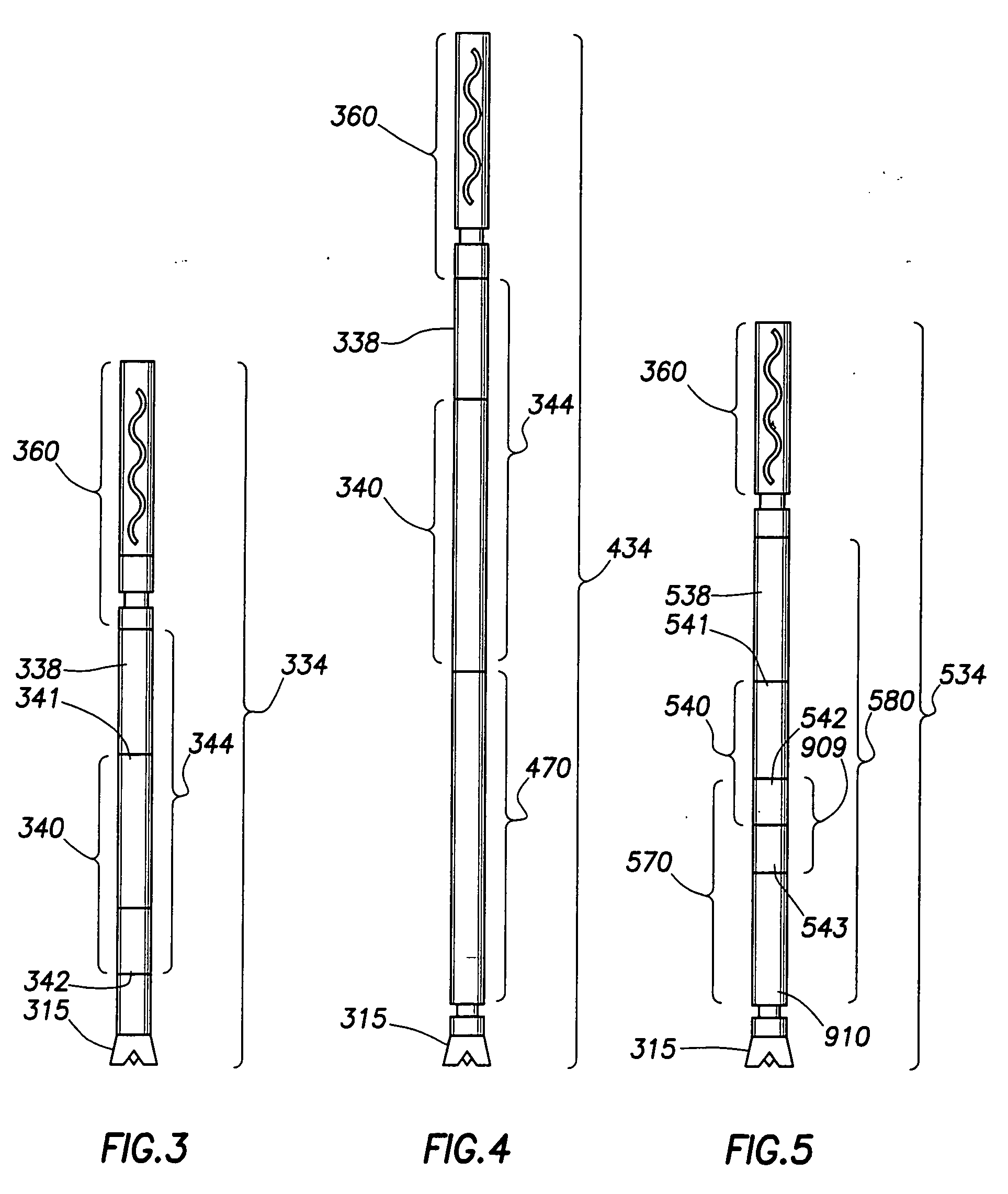
[0013] In response to the desires and needs identified herein, as well as other shortcomings in the relevant art, the present invention in its various aspects is generally directed to the placement of measuring sensors and telemetry systems in relatively close proximity to a drill bit, so as to improve cost efficiency as well as drilling performance. The present invention is adaptive to various drill strings, including conventional and casing drill strings, and is particularly suited for use in drill strings employing directional drilling systems such as mud motors and / or RSS.

Problems solved by technology

Adjustment of the borehole trajectory under these circumstances can be a difficult and costly task.
Since many of these elements are provided in a MWD tool, there will be some redundancy in a drill string employing a RSS with a MWD tool.
This often dictates that the drill string be rotated at speeds that approach the limits of the rotary table, thereby increasing the wear on the drill string and the casing.
This process is very time consuming and costly.
Additionally, other problems are often encountered when tripping the drill string.
For example, the drill string (or a portion thereof) may get stuck in the borehole while it is being removed.
These problems require additional time and expense to resolve.

Method used


Image

  • Apparatus and method for measuring while drilling
  • Apparatus and method for measuring while drilling
  • Apparatus and method for measuring while drilling

Examples


Embodiment Construction

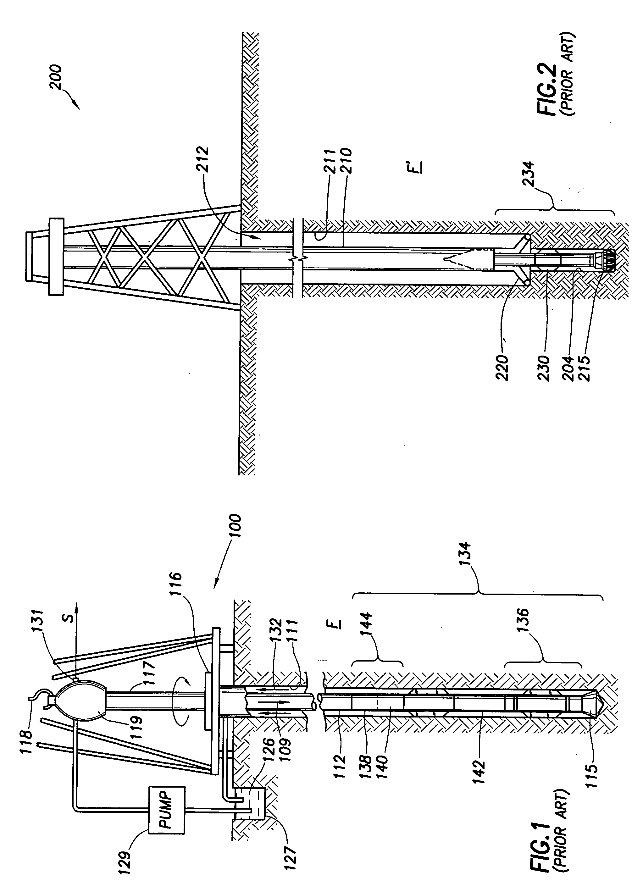
[0032]FIG. 1 illustrates a conventional drilling rig and drill string in which the present invention can be utilized to advantage. A land-based platform and derrick assembly 100 are positioned over a borehole 111 penetrating a subsurface formation F. In the illustrated embodiment, the borehole 111 is formed by rotary drilling in a manner that is well known. Those of ordinary skill in the art given the benefit of this disclosure will appreciate, however, that the present invention also finds application in drilling applications other than conventional rotary drilling (e.g., mud-motor based directional drilling, and / or rotary-steerable drilling, as described elsewhere herein), and is not limited to land-based rigs.

[0033] A drill string 112 is suspended within the borehole 111 and includes a drill bit 115 at its lower end. The drill string 112 is rotated by a rotary table 116, energized by means not shown, which engages a kelly 117 at the upper end of the drill string. The drill strin...


PUM


Abstract

An apparatus, system, and method for transmitting measurements while drilling are adapted for use with a drill string equipped with a mud motor. The drill string may comprise a plurality of interconnected drill pipe joints or a plurality of interconnected casing joints. The apparatus comprises a measurement-while-drilling tool adapted for placement in the drill string beneath the mud motor. The measurement-while-drilling tool has a system for transmitting telemetry signals, such as mud-pulse telemetry signals, upwardly through the mud motor and the drill string. In particular embodiments, the measurement-while-drilling tool has a system for transmitting mud-pulse telemetry signals upwardly through the mud motor and the drill string at frequencies below approximately 1 Hz, although other frequencies may be employed to advantage. The apparatus may further comprise a rotary steerable system for placement in the drill string beneath the mud motor. The rotary steerable system may be a point-the-bit system or a push-the-bit system. In particular embodiments, the rotary steerable system and the measurement-while-drilling tool are integrated.

Description

BACKGROUND OF THE INVENTION [0001] 1. Field of the Invention [0002] This invention relates generally to an apparatus and method for making downhole measurements during the drilling of a wellbore. More particularly, it relates to an apparatus and method for making downhole measurements at or near the drill bit during directional drilling of a wellbore. [0003] 2. Background of the Related Art [0004] The drilling of oil and gas prospecting wells, also know as “boreholes,” typically involves the use of a drilling assembly—particularly a directional drilling assembly—for penetrating one or more subsurface formations of interest. Such drilling assemblies, also known as “drill strings,” typically include lower sections known as “bottom-hole assemblies” or BHAs. A BHA may consist (generally from the bottom up in a vertical borehole section) of a drill bit, bit sub, stabilizers, drill collars, directional drilling equipment, measurement-while-drilling (MWD) tools, logging-while-drilling (LWD...

Claims


Application Information

Patent Timeline
IPC IPC(8): E21B49/00
CPCE21B47/18E21B7/068E21B4/02E21B7/06E21B47/20
Inventor MORIARTY, KEITH A.
Owner SCHLUMBERGER TECH CORP
Learn More