
Method and apparatus for dark current and blooming suppression in 4T CMOS imager pixel

Active Publication Date: 2006-11-09
MICRON TECH INC
View PDF13 Cites 21 Cited by
  • Summary
  • Abstract
  • Description
  • Claims
  • Application Information

AI Technical Summary

Benefits of technology

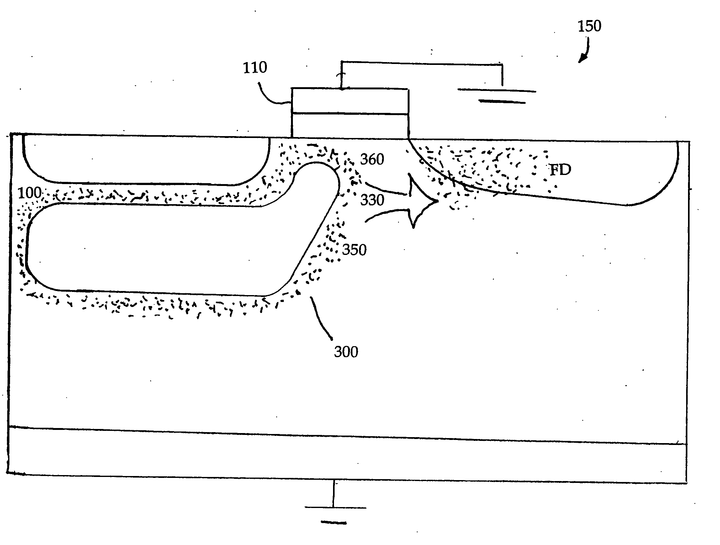
[0012] The invention provides a method of operating an imager pixel such that dark current and the factors that cause dark current in imagers are reduced. The invention permits a reduction in dark current without a reduction in pixel capacity and without causing blooming.
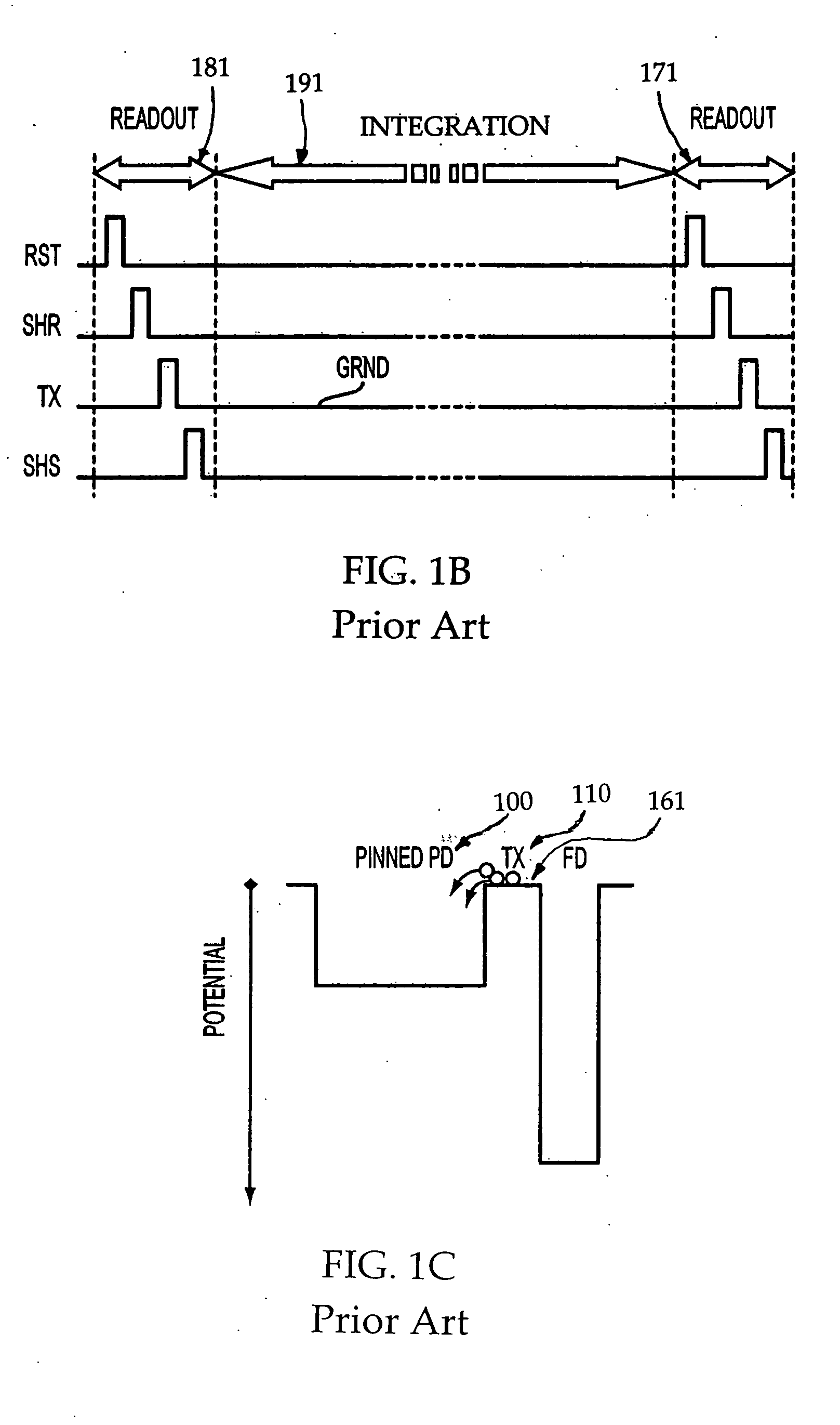
[0013] The above and other features and advantages are achieved in an exemplary embodiment of the invention by a method of operating an imager pixel that includes the act of applying a relatively small first voltage and a plurality of pulses of a second voltage on the gate of a transfer transistor during a charge integration period. The first voltage being a small negative voltage and the second voltage being a small positive voltage. When a small negative voltage is applied to the transfer gate, electrons that would normally create dark current problems will instead recombine with holes thereby substantially reducing dark current. When the small positive voltage pulses are applied, a depletion region is created under the transfer transistor gate, which creates a path for dark current electrons to be transferred to a pixel floating diffusion region.

Problems solved by technology

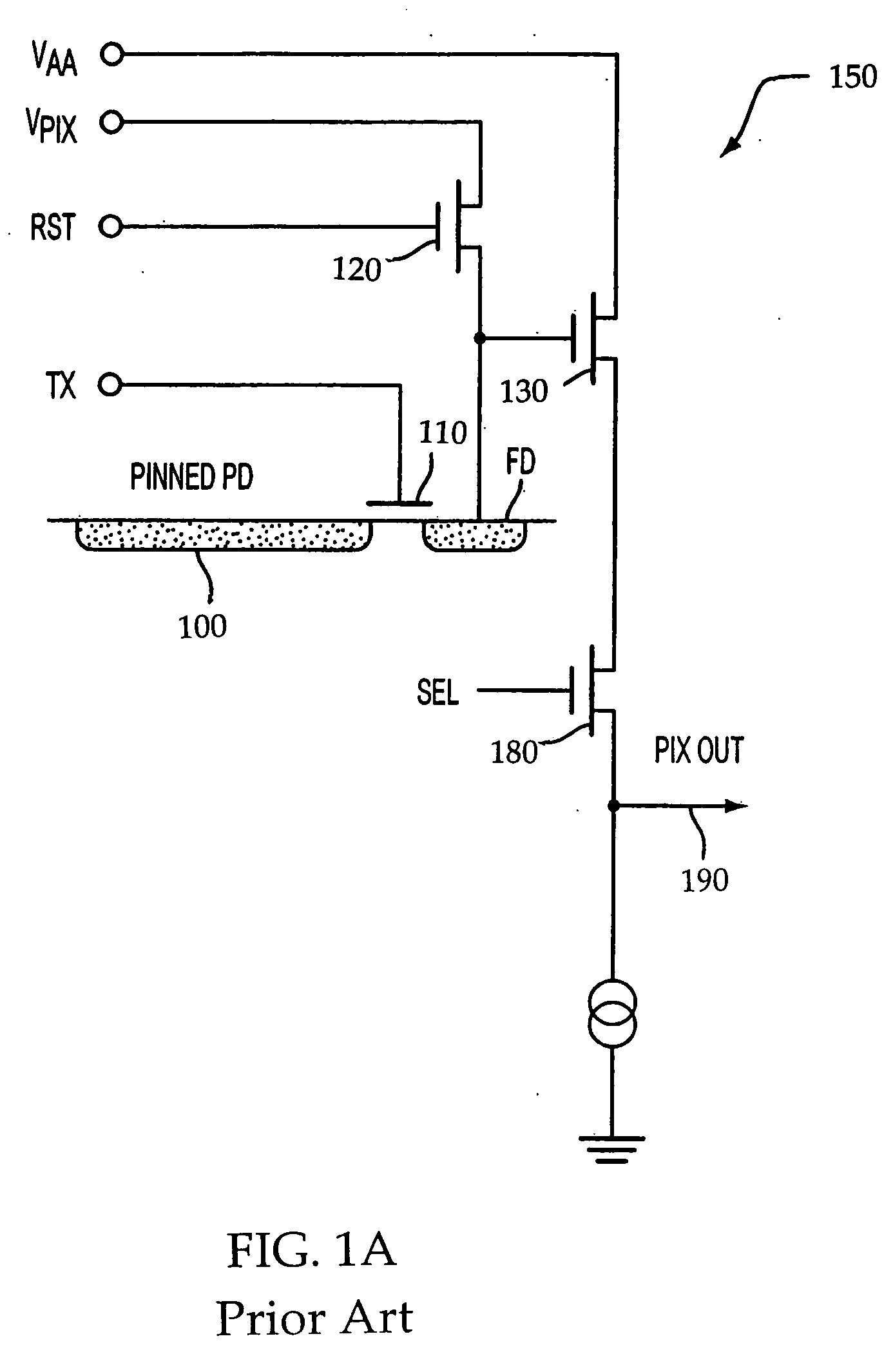
One common problem associated with conventional imager pixel cells, such as pixel cell 150, is dark current, that is, current generated as a photo-conversion device signal in the absence of light.
This defect causes increased thermal generation of electron-hole pairs, which may be collected in the photo-conversion device 100 (FIG. 1A) and effectively lower overall image quality.

Method used


Image

  • Method and apparatus for dark current and blooming suppression in 4T CMOS imager pixel
  • Method and apparatus for dark current and blooming suppression in 4T CMOS imager pixel
  • Method and apparatus for dark current and blooming suppression in 4T CMOS imager pixel

Examples


Embodiment Construction

[0024] In the following detailed description, reference is made to the accompanying drawings, which form a part hereof and illustrate specific embodiments in which the invention may be practiced. In the drawings, like reference numerals describe substantially similar components throughout the several views. These embodiments are described in sufficient detail to enable those skilled in the art to practice the invention, and it is to be understood that other embodiments may be utilized, and that structural, logical and electrical changes may be made without departing from the spirit and scope of the present invention.

[0025] The terms “wafer” and “substrate” are to be understood as including silicon, silicon-on-insulator (SOI), silicon-on-sapphire (SOS), and silicon-on-nothing (SON) technology, doped and undoped semiconductors, epitaxial layers of silicon supported by a base semiconductor foundation, and other semiconductor structures. Furthermore, when reference is made to a “wafer”...


PUM


Abstract

A method and apparatus for operating an imager pixel that includes the act of applying a relatively small first polarity voltage and a plurality of pulses of a second polarity voltage on the gate of a transfer transistor during a charge integration period.

Description

FIELD OF THE INVENTION [0001] The present invention relates generally to semiconductor devices, and more particularly, to dark current and blooming suppression in imager pixels. BACKGROUND OF THE INVENTION [0002] CMOS image sensors are increasingly being used as relatively low cost imaging devices. A CMOS image sensor circuit includes a focal plane array of pixel cells, each one of the cells includes a photo-conversion device, such as e.g., a photogate, photoconductor, or photodiode having an associated charge accumulation region within a substrate for accumulating photo-generated charge. Each pixel cell may include a transistor for transferring charge from the charge accumulation region to a sensing node, and a transistor for resetting the sensing node to a predetermined charge level prior to charge transference. The pixel cell may also include a source follower transistor for receiving and amplifying charge from the sensing node and an access transistor, for controlling the readou...

Claims


Application Information

Patent Timeline
IPC IPC(8): H01L29/04
CPCH04N5/361H04N5/3591H04N25/621H04N25/63H04N25/62H04N25/76
Inventor LADD, JOHN
Owner MICRON TECH INC
Learn More