
Method for producing a peripherally closed hollow profield element

a technology hollow profiles, which is applied in the field of method for producing a peripherally closed hollow profiled element, can solve the problems of inadequate relative sealing of blanks, and the inability to produce hollow profiled elements as desired, and achieve the effect of reliable production of hollow profiled elements

Inactive Publication Date: 2006-11-09
DAIMLER AG
View PDF10 Cites 1 Cited by
  • Summary
  • Abstract
  • Description
  • Claims
  • Application Information

AI Technical Summary

Benefits of technology

[0006] The object of the invention is to develop a method of the generic type to the effect that reliable production of the hollow profiled element is made possible even during pronounced compression deformations of the blank of the hollow profiled element, which result during the closing of the forming tool.
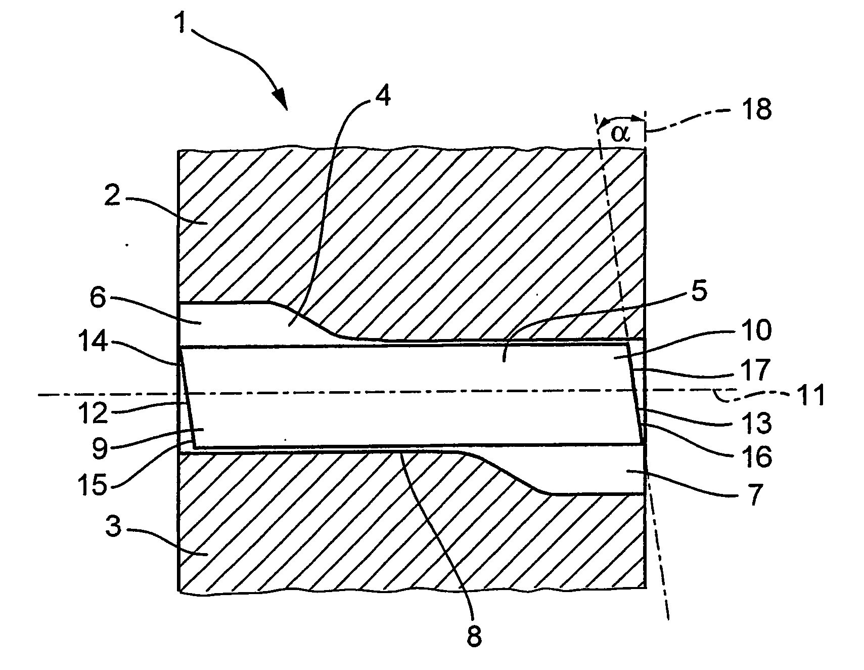
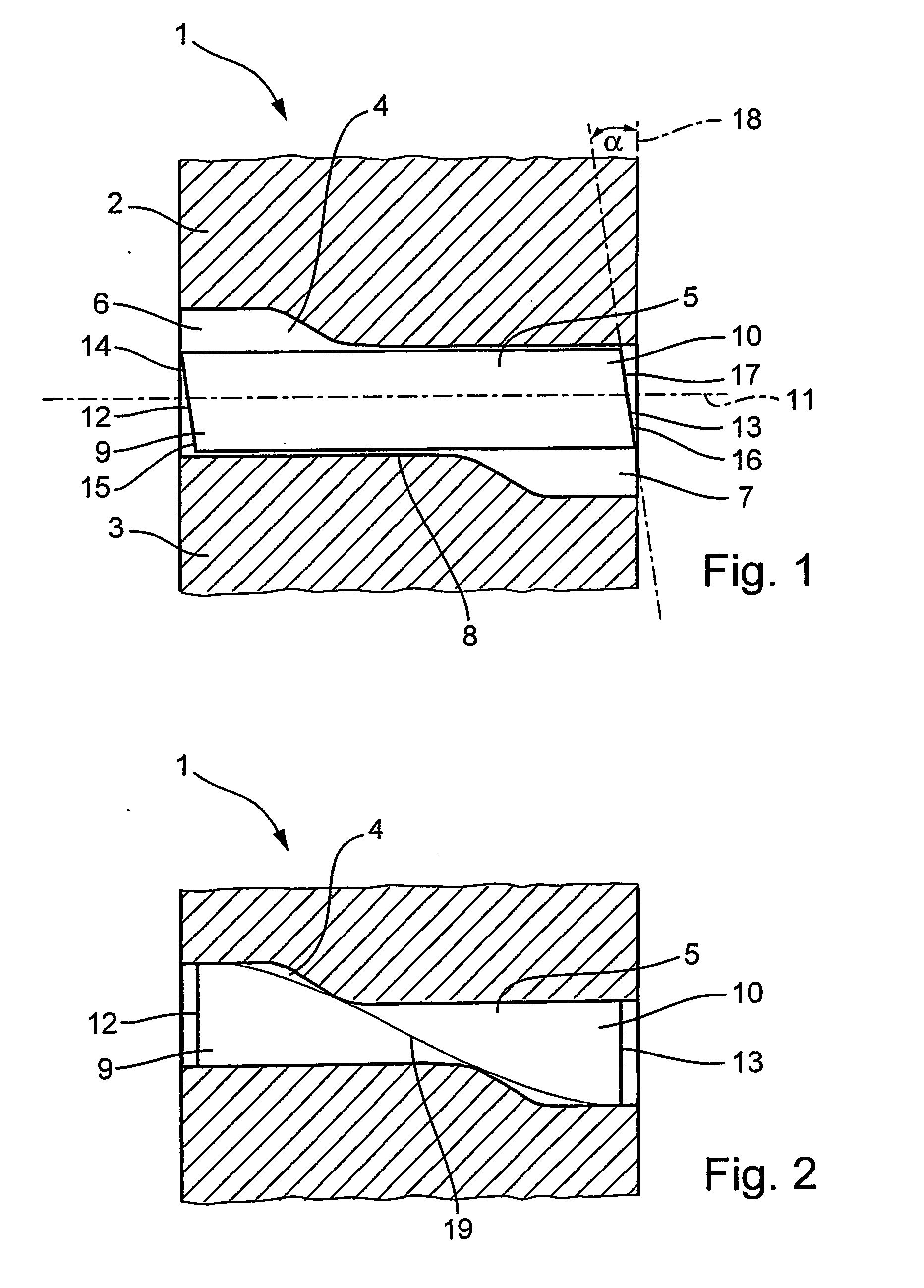
[0007] The invention is based on the knowledge that the deformations occurring during the compressing of the blank can be compensated for by the blank ends being cut to size in a specific manner. The trimming according to the invention of the blank ends achieves the effect that, after the compression and when the forming tool is completely closed, the front faces of the ends are flat and are as far as possible oriented perpendicularly to the longitudinal extent of the blank. As a result of the position of the blank ends which is achieved, the axial plungers can dock with these ends as if the blank had not been trimmed and had not been subjected to compression beforehand. The axial plungers can therefore sufficiently seal off the blank at both ends relative to the internal high pressure still to be produced, as a result of which reliable production of the hollow profiled element is made possible. In addition, a chip-removing collision between the axial plungers and the blank otherwise provided with tilted front faces is avoided by the invention, the chips and slivers which are produced in the process having to be removed in a complicated manner during a rework operation after removal of the finish-formed hollow profiled element. This removal usually involves severing of the sealing sections of the blank ends, so that such a trimming operation can be dispensed with on account of the invention, it being possible, in addition to saving labor, to save material scrap difficult to dispose of. It is also no longer necessary to plan in advance for a lost additional length of the blank, as a result of which the friction between blank and forming tool to be overcome during the subsequent expansion of the blank by means of internal high pressure is considerably reduced on account of the shorter length of the blank.
[0009] In a further preferred development of the invention, the blank ends are trimmed in such a way that their front faces remain arranged parallel to one another. In the event of the end regions of the blank of the hollow profiled element coming to lie vertically offset relative to one another after compression has been effected, the front face of the one untrimmed end is tilted upward, so that the bottom peripheral region projects axially beyond the top peripheral region of the end, and the front face of the other untrimmed end is tilted downward, the top peripheral region of the end projecting beyond the bottom peripheral region in the axial direction. The blank can therefore be trimmed at both ends at the same angle in the opposite direction of the tilting before the compression operation. The resulting homogeneity of the trimming at the same time makes the work during the cutting process easier. In addition, the same applies to a lateral offset of the ends after compression has been effected.
[0011] According to a further preferred embodiment of the invention, the end deformation actually occurring due to the subsequent compression operation is determined by a computer simulation, in particular a finite-element simulation, before the trimming of the ends and then an optimum trimming contour and an optimum beveling angle of the trimming to be effected is precisely calculated therefrom for compensating for the deformation. In this way, the beveling angle and trimming contour suitable for each component and for every type of compression can be determined individually relatively easily without resorting to numerous, laborious, empirical investigations.

Problems solved by technology

On account of the end contour changed by the compression and on account of the tilting of the front face, the axial plungers provided with a conical sealing region and subsequently docking with the ends of the blank can only seal off the blank inadequately relative to the internal high pressure subsequently to be produced.
The result of this is that the operation subsequently taking place for expanding the blank by means of the fluidic internal high pressure is not completely reliable and thus the hollow profiled element cannot be produced as desired.

Method used


Image

  • Method for producing a peripherally closed hollow profield element
  • Method for producing a peripherally closed hollow profield element

Examples


Embodiment Construction

[0017] Shown in FIG. 1 is an internal high-pressure forming tool 1 which consists of a top part 2 and a bottom part 3. The tool die cavity 4, which is formed by both tool parts 2 and 3 and defines a forming space for a blank 5 of a hollow profiled element to be formed which is inserted into the tool 1, is designed in such a way that one end 6 of the die cavity 4 is arranged vertically offset relative to the other end 7. In the closed forming tool 1 according to FIG. 2, these two ends 6 and 7 of the die cavity have approximately the same diameter as the inserted blank 5 of the hollow profiled element. The die cavity 4 is considerably constricted in cross section in a center region 8, which connects the two ends 6 and 7 to one another.

[0018] The blank 5 of the hollow profiled element has in turn, at its two ends 9 and 10, a respective front face 12 or 13 inclined in the direction of the longitudinal axis 11 of the blank 5 of the hollow profiled element. Whereas a top peripheral regio...


PUM

PropertyMeasurementUnit
beveling angleaaaaaaaaaa

Abstract

The invention relates to a method for producing a peripherally closed hollow profiled element by means of internal high-pressure forming, a hollow elongated blank (5) being inserted into an internal high-pressure forming tool (1), and the blank (5) located completely inside the forming tool (1) after the insertion being compressed in a region lying between its ends (9, 10) during the closing operation of the forming tool (1), after which the compressed blank (5) is expanded into the final shape of the hollow profiled element by means of fluidic internal high pressure. In order to permit reliable production of the hollow profiled element even during pronounced compression deformations of the blank (5) of the hollow profiled element, which are produced during the closing of the forming tool (1), it is proposed that the ends (9, 10) of the blank (5) be trimmed before the compression operation, with a respective beveled front face (12, 13) being formed, and that the trimming contour of the ends (9, 10) and the beveling angle (α) be selected in such a way that the ends (9, 10) are deformed by means of the compression operation in such a way that their front faces (12, 13) have an essentially plane form and assume a position which is as perpendicular as possible to the longitudinal extent of the blank (5).

Description

CROSS REFERENCE TO RELATED APPLICATION [0001] This application is a national stage of PCT / EP2004 / 004301 filed Apr. 23, 2004 and based upon DE 103 23 738.0 filed May 24, 2003 under the International Convention.BACKGROUND OF THE INVENTION [0002] 1. Field of the invention [0003] The invention relates to a method for producing a peripherally closed hollow profiled element. [0004] 2. Related Art of the invention [0005] A method of the generic type has been disclosed by WO 98 / 43758 A1. In this case, a blank of a hollow profiled element of uniform cross section is inserted into an internal high-pressure forming tool, the die cavity of which has a reduced cross section relative to the blank in the region between its ends. As a result, the inserted blank of the hollow profiled element is compressed in this region during the closing operation of the forming tool. However, the drawing-in, resulting from this, of the blank of the hollow profiled element manifests itself in inclination or deform...

Claims


Application Information

Patent Timeline
Patent Type & Authority Applications(United States)
IPC IPC(8): B21D28/18B21D26/033
CPCB21D26/053B21D26/033
Inventor LINKE, GERHARDSCHROEDER, MATTHIASSCHULT, JENS
Owner DAIMLER AG
Learn More