
Compliant metal support for ceramic combustor liner in a gas turbine engine

a technology of ceramic combustor and metal support, which is applied in the direction of machines/engines, mechanical equipment, lighting and heating apparatus, etc., can solve the problems of increasing pressure loss, reducing the air available for combustor liner cooling,

Inactive Publication Date: 2006-11-02
RAYTHEON TECH CORP
View PDF12 Cites 49 Cited by
  • Summary
  • Abstract
  • Description
  • Claims
  • Application Information

AI Technical Summary

Benefits of technology

[0006] Accordingly, it is an object of the present invention to provide a combustor system for an engine having a ceramic component and at least one metal component with a structure for controlling the thermal stresses which are produced.
[0007] It is a further object of the present invention to provide a structure as above which spreads the local contact stress in the attachment area by using a compliant interface layer.
[0008] It is yet a further object of the present invention to provide a structure as above which stops the reaction between the ceramic component and the metal component(s) by using an interface layer that is chemically non-reactive to both the ceramic component and the metal component(s).
[0010] In accordance with the present invention, a combustion system for an engine is provided. The combustion system broadly comprises a ceramic component, at least one metal support component for providing radial and axial support to the ceramic component, and the at least one metal support component having means for minimizing stress and for increasing compliance of the metal support component with respect to the ceramic component.

Problems solved by technology

Such a lean combustion reduces the air available for combustor liner cooling and / or increases pressure loss during the cooling of the combustor liner.
Thermal stress arising from the mismatch of the CTEs poses a challenge to the insertion of ceramic combustor liner into gas turbine engines.

Method used


Image

  • Compliant metal support for ceramic combustor liner in a gas turbine engine
  • Compliant metal support for ceramic combustor liner in a gas turbine engine
  • Compliant metal support for ceramic combustor liner in a gas turbine engine

Examples


Embodiment Construction

)

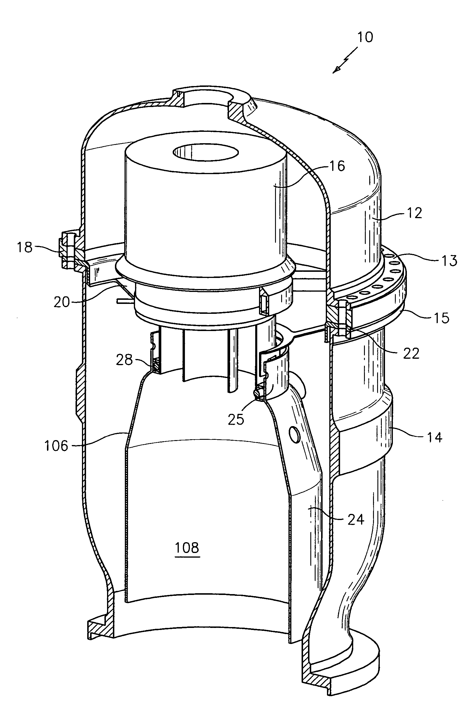
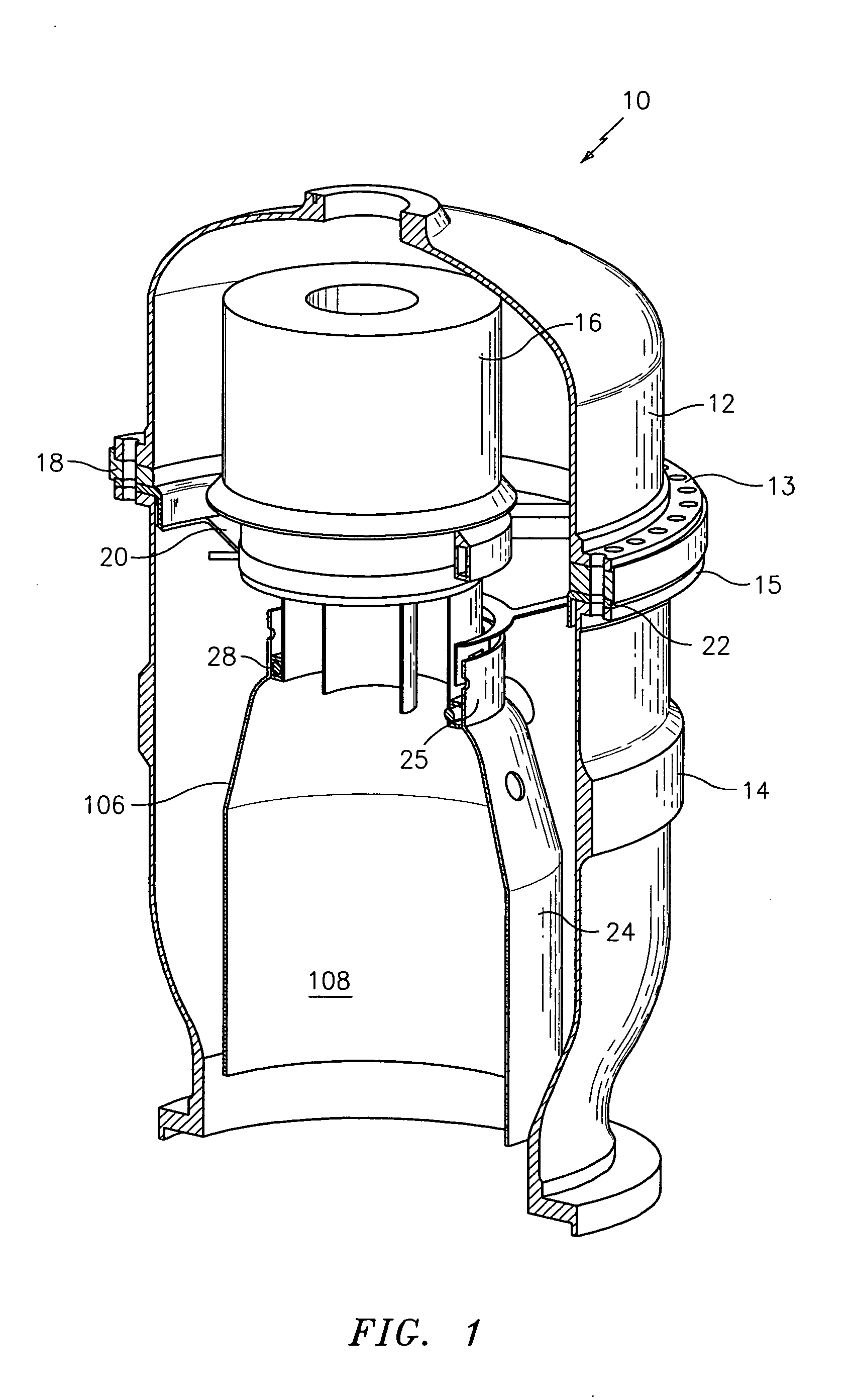
[0022] Referring now to the drawings, FIGS. 1-3 illustrate a first embodiment of a portion of a combustion system of an engine, such as a gas turbine engine. Within the engine, the combustion system is positioned intermediate the compressor section(s) and the turbine section(s) of the engine. In the combustion section, pressurized air is received from the compressor section(s) and mixed with fuel in a known manner.

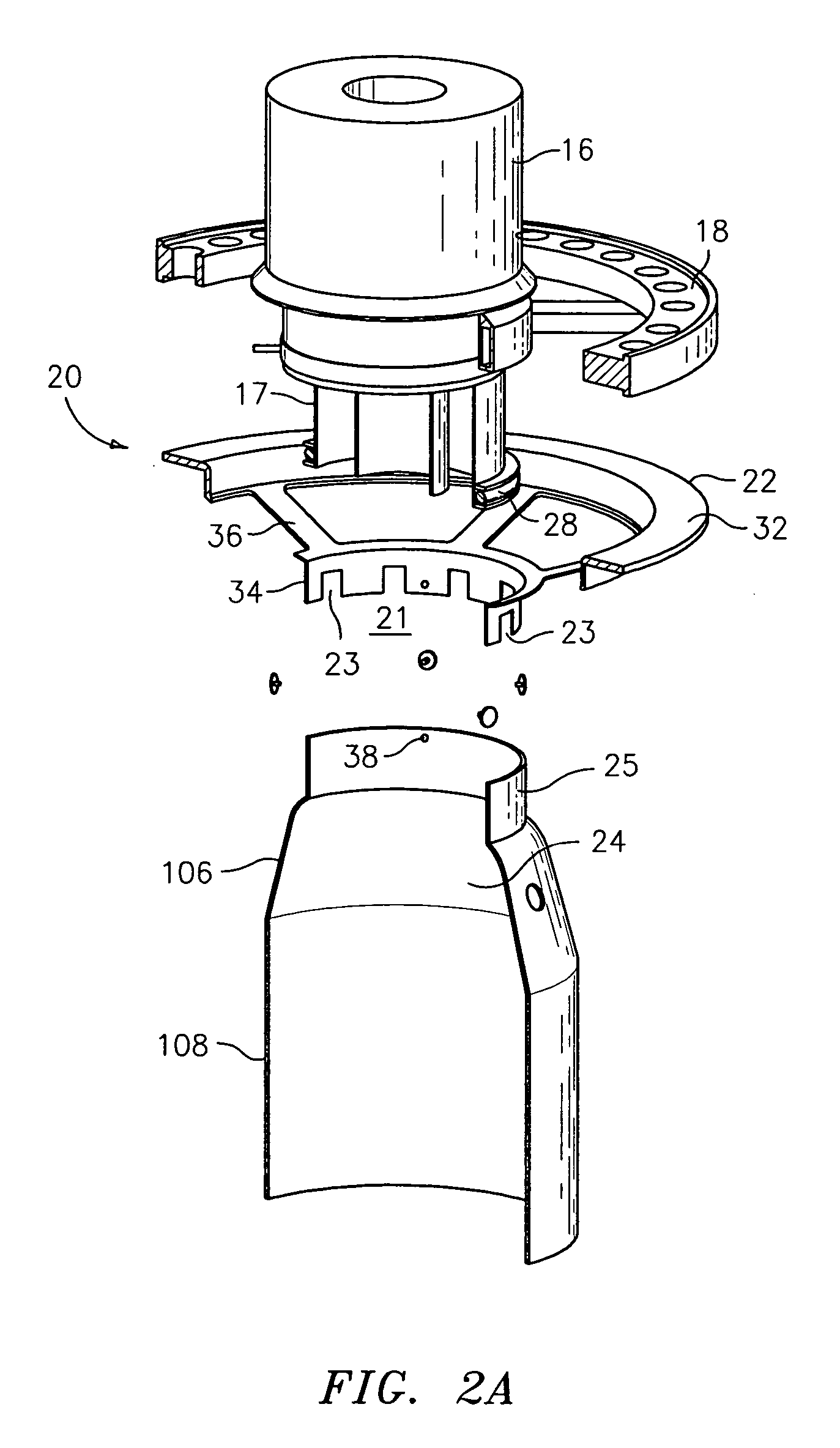
[0023] Referring now to FIG. 1, a combustion system 10 in accordance with the present invention may include an upper metal casing 12, a lower metal casing 14, a fuel air pre-mixer 16, a fuel supply manifold 18, a metal support ring 20 and a ceramic combustor liner 24. FIG. 2 depicts an exploded view of the combustion system 10 of FIG. 1 without the upper and lower metal casings 12 and 14.

[0024] As best shown in FIG. 2, the metal support ring 20 has an upper annular member 32 and a lower annular member 34. The upper member 32 and the lower member 34 are joined together b...


PUM

PropertyMeasurementUnit
stressaaaaaaaaaa
temperatureaaaaaaaaaa
temperaturesaaaaaaaaaa

Abstract

A combustion system for an engine, such as a gas turbine engine is provided. The combustion system has a ceramic component, such as ceramic combustor liner, and at least one metal support component, such as a metal ring or a plurality of metal cones, for providing radial and axial support to the ceramic component. The at least one metal support component includes a structure, such as axial slots or radial slots, for minimizing stress and for increasing compliance of the metal support component with respect to the ceramic component.

Description

BACKGROUND OF THE INVENTION [0001] (1) Field of the Invention [0002] The present invention relates to a combustion system for an engine, such as a gas turbine engine, and more particularly, to a compliant metal support for a ceramic combustor liner used in the combustion system. [0003] (2) Prior Art [0004] A gas turbine engine consists of an inlet, a compressor, a combustor, a turbine, and an exhaust. The compressor draws in ambient air and increases its temperature and pressure. Fuel is added to the compressed air in the combustor to further raise gas temperature. The high temperature gas expands in the turbine to extract work that drives the compressor and other mechanical devices such as an electric generator. [0005] To reduce NOx produced in the combustor, it is desirable to reduce flame temperature. This requires a high percentage of the compressed air to be mixed with the fuel to produce a lean fuel air mixture. Such a lean combustion reduces the air available for combustor li...

Claims


Application Information

Patent Timeline
Patent Type & Authority Applications(United States)
IPC IPC(8): F23R3/42
CPCF23R3/60F23R3/007
Inventor SHI, JUNLAWRENCE, JASONBOMBARA, DAVID J.TUTHILL, RICHARD S.MELMAN, JEFFREY D.
Owner RAYTHEON TECH CORP
Learn More