
Friction material

a technology of friction material and friction lining, which is applied in the field of friction material, can solve the problems of high energy requirements and inability to achieve the optimum performance of friction material, and achieve the effects of stable and consistent frictional performance, high heat resistance, and rapid heat dissipation

Active Publication Date: 2006-10-26
BORGWARNER INC
View PDF99 Cites 27 Cited by
  • Summary
  • Abstract
  • Description
  • Claims
  • Application Information

AI Technical Summary

Benefits of technology

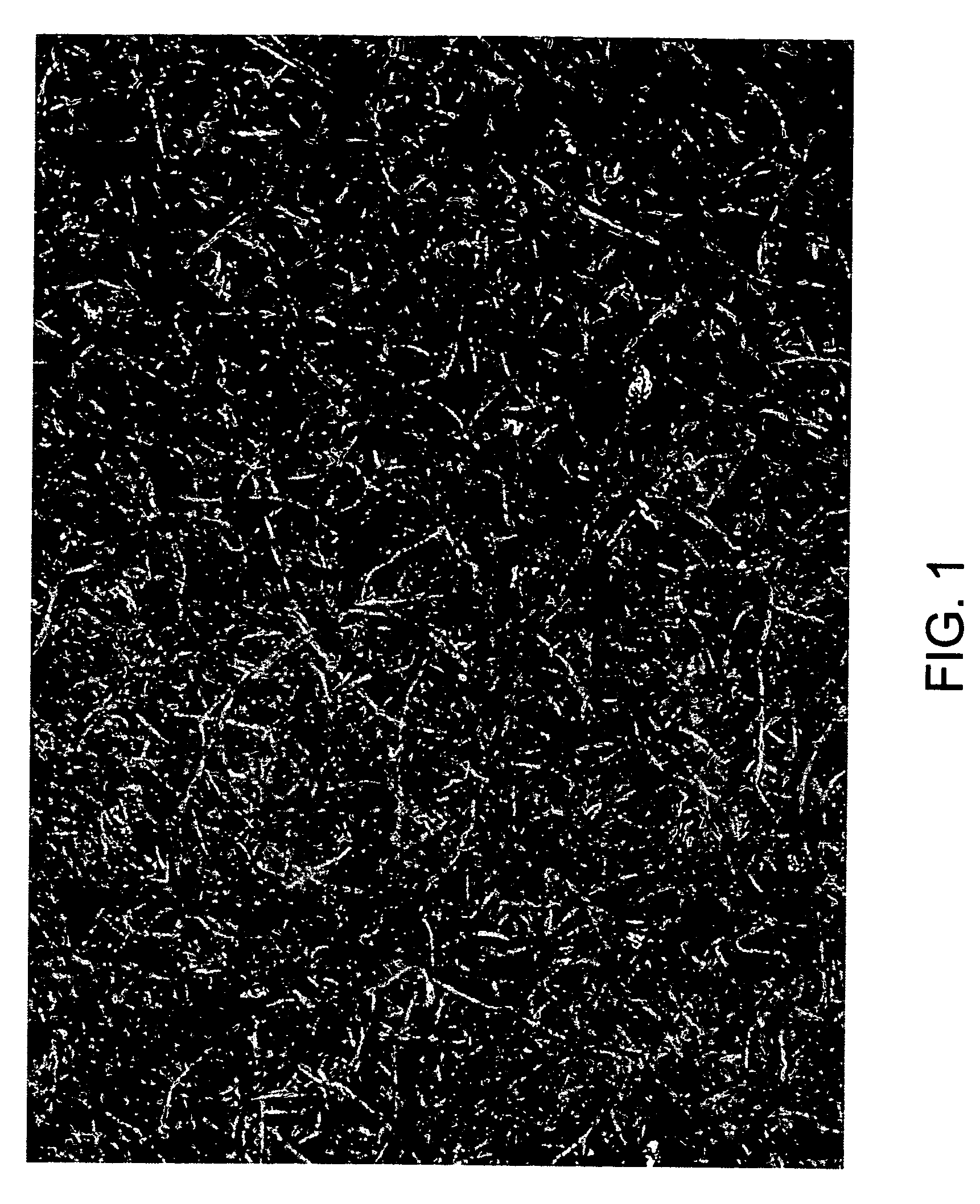
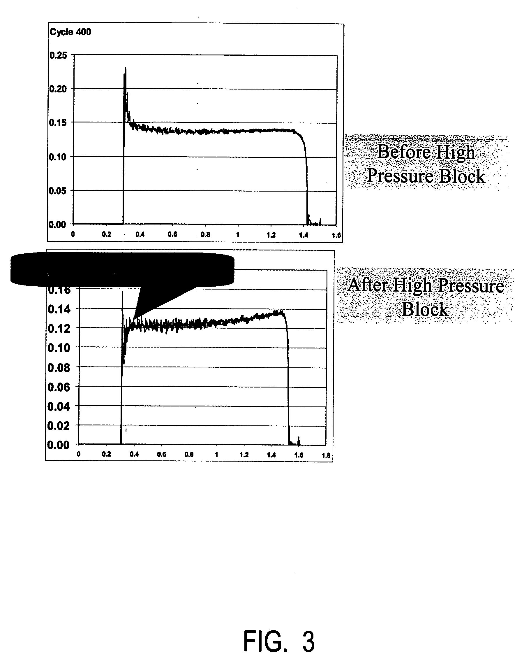
[0010] The friction material of this invention is a wet friction material for use in a fluid environment. The wet material comprises a fibrous base material of small diameter fibers having a fiber diameter ranging from 1 to 20 micrometers, wherein the small diameter fibers have a tensile modulus greater than 70 Gpa. Preferably the fiber diameter ranges from 1 to 10 micrometers and the tensile modulus ranges from 150 to 350 Gpa. Preferably, the small diameter fibers are a combination of small diameter carbon fibers and small diameter ceramic, silica or mineral fibers. The wet friction material of this invention has long lasting, stable and consistent frictional performance in a high energy, high pressure oiled environment. Preferably, the high pressure oiled environment is greater than 4 MPa.

Problems solved by technology

These new systems often involve high energy requirements.
If any of these characteristics are not met, optimum performance of the friction material is not achieved.

Method used


Image

  • Friction material
  • Friction material
  • Friction material

Examples


example 1

[0062] In certain embodiments, the friction material can comprise a fibrous base material comprising, by weight percent: about 20 to about 60% fibrillated aramid fibers, about 10 to about 30% silica filler material, about 10 to about 20% graphite, and about 5 to about 20% small diameter sized petroleum pitch-based carbon fibers. One embodiment of the present invention comprises fibrillated aramid fiber at about 50%, silica filler at about 20%, graphite at about 15%, small diameter petroleum pitch-based carbon fiber at about 15%, and optionally latex at about 2% add on was used to make a fibrous base material having a basis weight of about 155 lb / 3000 ft2 and having a caliper of about 29 mils.

[0063]FIG. 5 is a test showing a shifting clutch application showing a coefficient of friction for two examples of small diameter carbon fibers and a comparative larger diameter standard carbon fiber for different cycles. The results clearly show improved compressive strength for the small diam...

example 2

[0067] In certain embodiments, the friction material can comprise a fibrous base material comprising, by weight percent: about 20 to about 60% fibrillated aramid fibers, about 10 to about 30% silica filler material, about 10 to about 20% graphite, and about 5 to about 20% small diameter mineral fibers.

[0068]FIG. 6 is a test showing material properties for coefficient of friction for examples of small diameter mineral fibers and prior art larger diameter conventional fibers.

example 3

[0069] In certain embodiments, the friction material can comprise a fibrous base material comprising, by weight percent: about 20 to about 60% fibrillated aramid fibers, about 10 to about 30% silica filler material, about 10 to about 20% graphite, and about 5 to about 20% small diameter ceramic fibers.

[0070]FIG. 7 is a test showing coefficient of friction for examples of small diameter mineral fibers having improved friction recovery over larger diameter conventional fibers.


PUM

PropertyMeasurementUnit
Percent by massaaaaaaaaaa
Pressureaaaaaaaaaa

Abstract

This friction material has a fibrous base material and preferably is a wet friction material for use in a fluid environment. The fibers have a small diameter and a high tensile modulus resulting in flexible fibers that performs well in a high temperature, high pressure fluid environment. The fibers have a diameter ranging from 1 to 20 micrometers and a tensile modulus greater than 70 Gpa. In the preferred embodiment, the small diameter fibers are small diameter carbon fibers or small diameter mineral fibers.

Description

CROSS REFERENCE TO PRIOR APPLICATION [0001] This application claims the benefit of provisional patent application Ser. No. 60 / 674,934 filed Apr. 26, 2005 and Ser. No. 60 / 723,314 filed Oct. 4, 2005.TECHNICAL FIELD [0002] The present invention relates to a friction material having a fibrous base material. In a preferred embodiment, the fibers have a small diameter and a high tensile modulus resulting in flexible fibers that performs well in a high temperature, high pressure fluid environment. BACKGROUND OF THE INVENTION [0003] New and advanced continuous torque transmission systems, having continuous slip torque converters and shifting clutch systems are being developed by the automotive industry. These new systems often involve high energy requirements. Therefore, the friction materials technology must be also developed to meet the increasing energy requirements of these advanced systems. [0004] In particular, a new high performance, durable friction material is needed. The new frict...

Claims


Application Information

Patent Timeline
IPC IPC(8): C08J5/14
CPCC08J5/04C08J2361/00F16D69/026D06M11/79D06M11/74F16D13/60C08J5/00
Inventor LAM, ROBERT C.DONG, FENG
Owner BORGWARNER INC
Learn More