
Reflection type terahertz spectrometer and spectrometric method

a terahertz spectrometer and spectrometer technology, applied in the direction of optical radiation measurement, polarisation spectroscopy, instruments, etc., can solve the problems of phase shift error, sample limited to solids, liquids, amorphous living organisms or the like cannot be measured,

Inactive Publication Date: 2006-10-19
AISIN SEIKI KK
View PDF11 Cites 76 Cited by
  • Summary
  • Abstract
  • Description
  • Claims
  • Application Information

AI Technical Summary

Benefits of technology

[0012] By thus forming the irradiating means, terahertz wave absorption loss inside the irradiating means can be decreased.
[0014] Due to their long wavelengths, terahertz waves are strongly absorbed by atmospheric H2O, etc., which becomes noise in terahertz spectrometry. However, the inner space of the housing can be purged with nitrogen, etc. or vacuumed, and as a result absorption by H2O, etc. can be prevented.

Problems solved by technology

The most important problem of this spectrometer is that an error occurs in phase shift unless measurement is conducted with the metallic mirror and the sample placed in exactly the same position.
Besides, its samples are limited to solids.
And liquid, amorphous living organisms or the like cannot be measured.
As mentioned above, the conventional reflection-type terahertz spectrometer requires the sample and the metallic mirror to be placed in the same position and has made large measurement errors.
This placement takes a lot of time and this spectrometer is poor in practicality.
In addition, since its samples are limited to solids, this spectrometer is poor in general versatility.

Method used


Image

  • Reflection type terahertz spectrometer and spectrometric method
  • Reflection type terahertz spectrometer and spectrometric method
  • Reflection type terahertz spectrometer and spectrometric method

Examples


first preferred embodiment

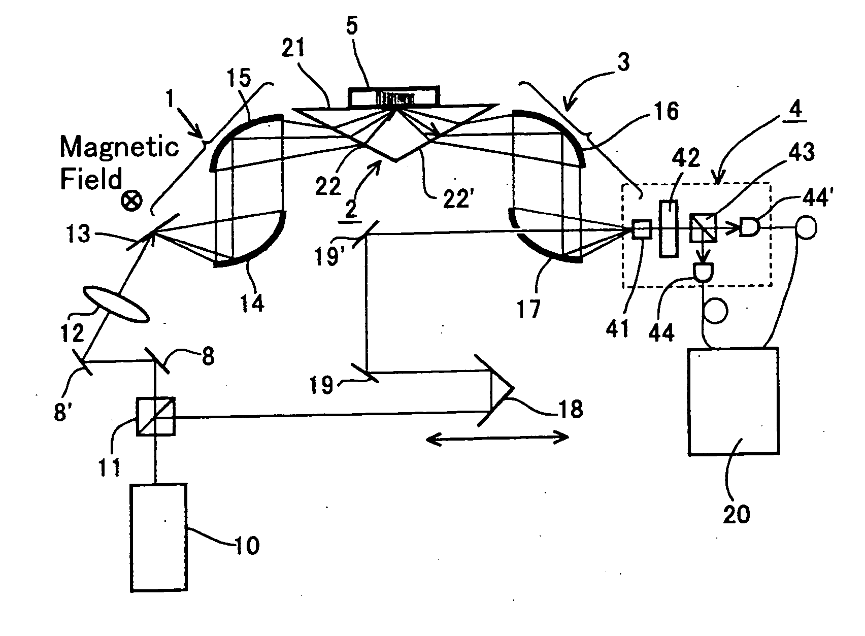
[0039]FIG. 1 is a schematic view showing the structure of a reflection-type terahertz spectrometer according to a preferred embodiment of the present invention.

[0040] The spectrometer of this preferred embodiment comprises an input optical path 1 through which terahertz waves from a terahertz wave generating means 13 are propagated, an irradiating means 2 which irradiates a sample 5 with the terahertz waves propagated through the input optical path 1, an output optical path through which terahertz waves having exiting from the irradiating means 2 are propagated, and a detecting means 4 which receives and detects the terahertz waves propagated through the output optical path 3.

[0041] The terahertz wave generating means 13 is a bulk semiconductor InAs in which ultrashort light pulses with a wavelength of 800 nm, a pulse width of 100 fs, a repetition of 80 MHz from a femtosecond laser light source 10 are split in half by a polarization beam splitter 11, bent by bend mirrors 8, 8′ and...

second preferred embodiment

[0047]FIG. 5 is a schematic diagram showing the structure of the reflection-type terahertz spectrometer according to a second embodiment of the present invention. Although the spectrometer of the first preferred embodiment was affected by absorption by atmospheric H2O, the spectrometer of the second preferred embodiment is constructed so as not to be affected by absorption by H2O. Hence, the spectrometer of the second preferred embodiment comprises a housing 6 which isolates the input optical path 1, the irradiating means 2 and the output optical path 3 of the first preferred embodiment (shown in FIG. 1) from the outside. In FIG. 5, the same constitutional elements as those of the first preferred embodiment are denoted by the same reference numerals as those of FIG. 1 and repetition of description is omitted.

[0048] The housing 6 comprises an opening 61, windows 62, 62′, a gas inlet valve 63 and a gas exhaust valve 64, and the opening 61 is sealed with the planar interface 21 of the...

third preferred embodiment

[0049]FIG. 6 is a schematic diagram showing the structure of a reflection-type terahertz spectrometer according to a third preferred embodiment of the present invention. The spectrometer of this preferred embodiment is constructed so as to be capable of observing an absorption spectrum by plasma, longitudinal phonons in a semiconductor, etc. Hence, the spectrometer of this preferred embodiment comprises a polarizer 7, which is a polarization control means, on the input optical path 1 of the first preferred embodiment (shown in FIG. 1). In FIG. 6, the same constitutional elements as those of the first preferred embodiment are denoted by the same reference numerals as those of FIG. 1 and repetition of description is omitted.

[0050] A compound semiconductor GaAs was used as a sample 5. First the terahertz waves which were p-polarized by controlling the polarizer 7 were made incident on the side 22 of the prism 2 and a spectrum was measured. Next, the terahertz waves which were s-polari...


PUM


Abstract

A reflection-type terahertz spectrometer includes an input optical path through which terahertz waves are propagated, an irradiating mechanism that irradiates a sample with terahertz waves propagated through the input optical path, an output optical path through which terahertz waves exiting from the irradiating mechanism are propagated, and a detector that receives and detects the terahertz waves propagated through the output optical path. The irradiating mechanism has at least one planar interface and a refractive index greater than that of a peripheral region contacting the planar interface and is disposed between the input optical path and the output optical path such that the terahertz waves propagated through the input optical path to be incident on the planar interface undergo total internal reflection at the planar interface, and the sample is disposed in the peripheral region contacting the planar interface of the irradiating mechanism. When the terahertz waves undergo the total internal reflection at the planar interface, the sample is irradiated with evanescent waves scattering from the planar interface to the peripheral region contacting the planar interface, so as to measure a spectrum.

Description

TECHNICAL FIELD [0001] The present invention relates to an instrument and a method which measures a spectrum of a sample under analysis in a terahertz frequency range. BACKGROUND ART [0002] Terahertz waves are electromagnetic waves with frequencies between 0.1 and 10 THz (wavelengths between 30 μm and 3000 μm). This wavelength range approximately corresponds to the infrared to far infrared region. Terahertz spectrometers using these terahertz waves have been developed. [0003] The terahertz spectrometers are divided into a transmission type which irradiates terahertz waves on a sample and detects transmitted light, and a reflection type which irradiates terahertz waves on a sample and detects reflected light. The transmission-type spectrometers need samples to be in the form of a thin film of about 1 μm, since terahertz waves, which fall in the infrared to far infrared region, are strongly absorbed by most substances. Therefore, much attention has been paid to the reflection-type spe...

Claims


Application Information

Patent Timeline
IPC IPC(8): G01J5/02G01J3/447G01J3/42G01N21/27G01N21/35G01N21/3586G01N21/552
CPCG01N21/552G01N21/3581
Inventor OHTAKE, HIDEYUKIYOSHIDA, MAKOTOTANAKA, KOICHIRONAGAI, MASAYA
Owner AISIN SEIKI KK
Learn More