
Recording tape cartridge

a technology of recording tape and cartridge, which is applied in the field of recording tape cartridge, can solve the problems of recording tape cartridge damage, drive device malfunction, recording tape tends to wrinkle or become torn, and the recording/playback cannot be performed, etc., and achieves the effect of fluctuating the resistance to sliding of the lock member

Active Publication Date: 2006-10-19
FUJIFILM CORP +1
View PDF6 Cites 9 Cited by
  • Summary
  • Abstract
  • Description
  • Claims
  • Application Information

AI Technical Summary

Benefits of technology

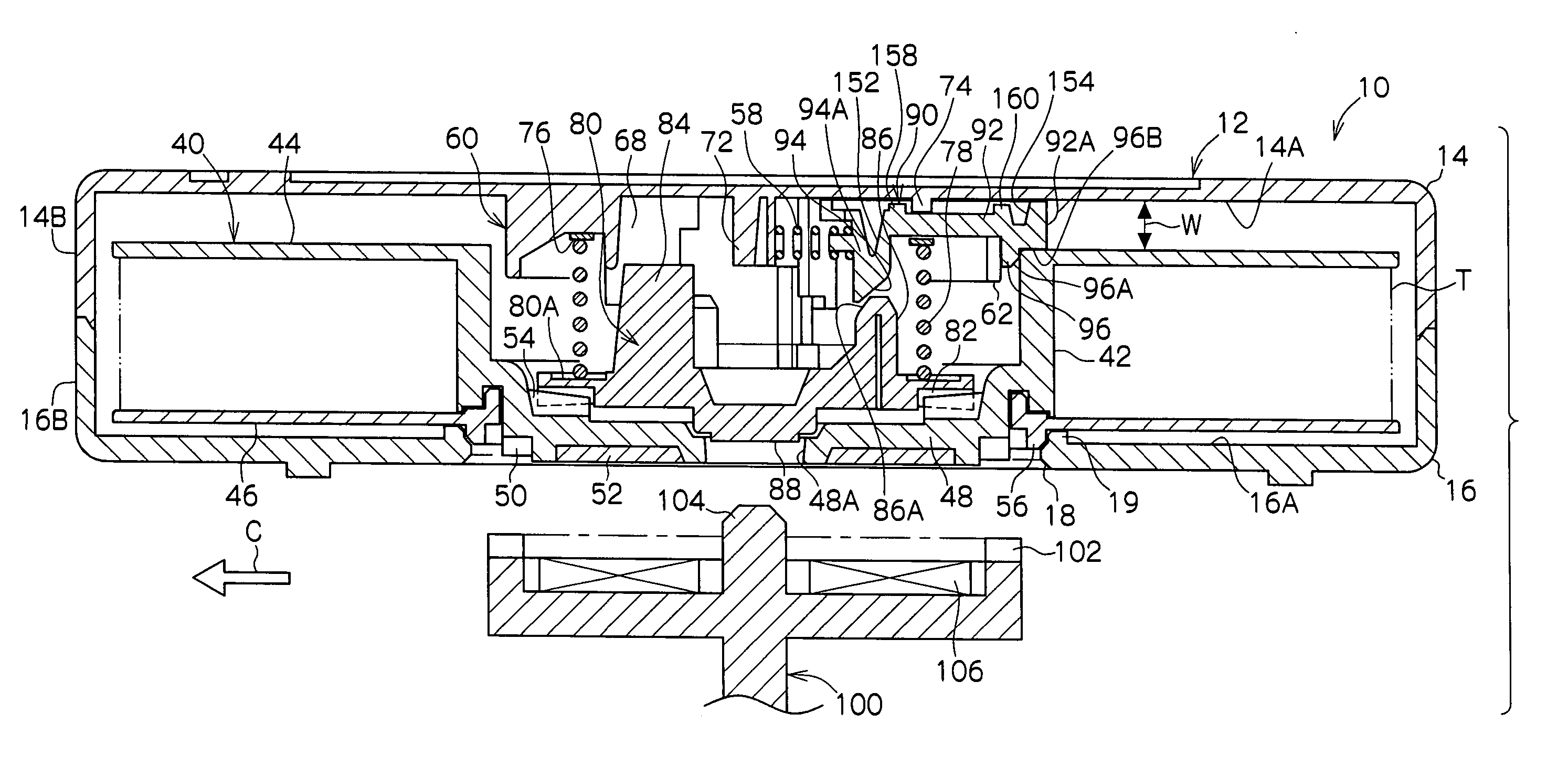
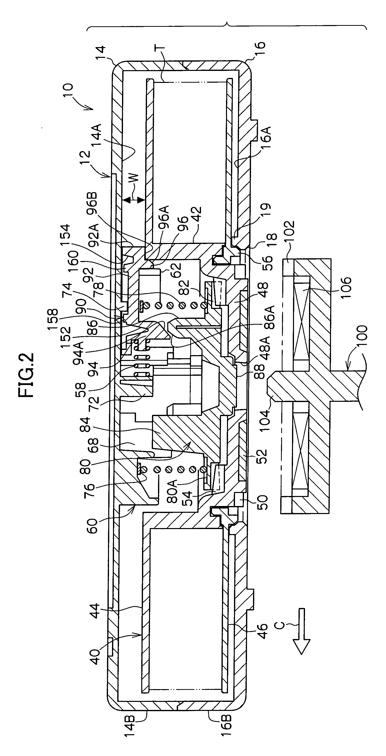
[0017] In other words, when compared to a case when the inclines S1, S2 of the brake member and the lock member mutually contact with surface-to-surface contact, the area of contact between the brake member and the lock member is small and abrasion due to sliding of the lock member can be reduced. For this reason, increases in resistance to sliding due to abrasion can be avoided and increases in the releasing force required to release the reel from a state of non-use can be prevented.
[0022] In other words, fluctuations in the resistance to sliding of the lock member from when the lock member begins to move until immediately prior to the lock member slipping down from the brake member are minimized by changing the position of contact between the lock member and the brake member by means of the movement of the lock member.

Problems solved by technology

If the recording tape cartridge is loaded into a drive device in such a condition, the problem exists that either recording / playback can simply not be performed or, moreover, that the recording tape cartridge is damaged or the drive device malfunctions.
A further problem is that since the reel becomes rotatable when not in use, the recording tape tends to become wrinkled or is torn.

Method used


Image

  • Recording tape cartridge
  • Recording tape cartridge
  • Recording tape cartridge

Examples


Embodiment Construction

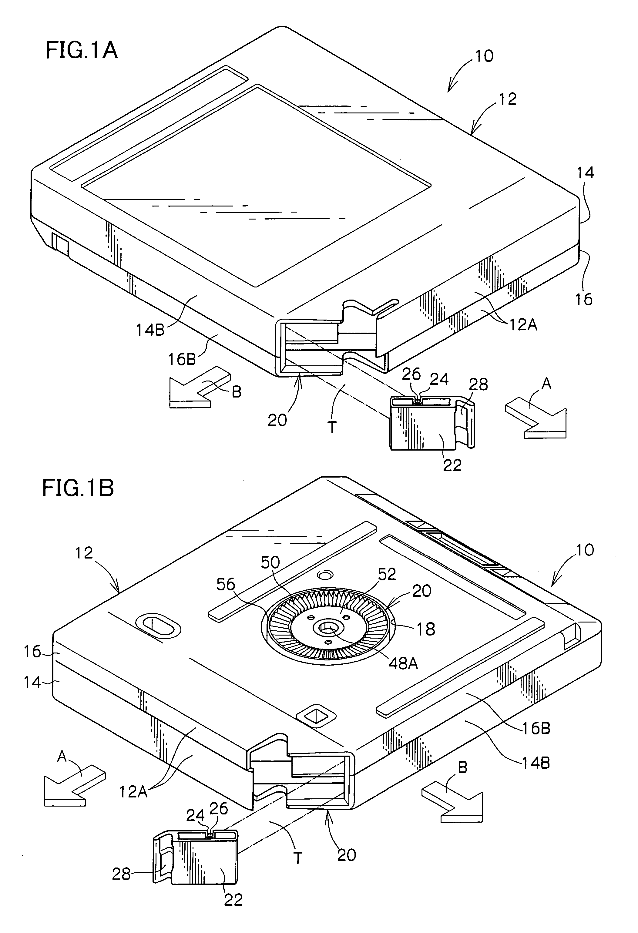
[0053] In the following, embodiments of the present invention will be explained in detail based on the examples shown in the drawings. Further, the reel according to the present invention is applicable to a recording tape cartridge 10. Accordingly, for convenience of explanation, the direction of loading the recording tape cartridge 10 into a drive device is taken as the forward direction and shown by Arrow A. Arrow B, which is orthogonal to Arrow A, is taken as the right-hand direction.

[0054] Firstly, the overall structure of the recording tape cartridge 10 will be explained. As shown in FIGS. 1 to 4, the recording tape cartridge 10 has a substantially rectangular box-shaped case 12. The case 12 is formed by joining a plastic upper casing 14 with a plastic lower casing 16 by ultrasonic welding, screw fastening, or the like, such that respective peripheral walls 14B and 16B of the upper casing 14 and the lower casing 16 are mutually abutted.

[0055] A reel 40 is singly accommodated ...


PUM


Abstract

In a recording tape cartridge, a compression coil spring urges a reel downward via a brake member. Due to the biasing force of the spring, a gear of the brake member securely meshes with a gear inside a reel hub preventing the reel's inadvertent rotation. The biasing force urges lock members outward in a radial direction from the center of a mount or the reel. Engagement portions of the lock members engage with an upper edge of the hub. The outer side surfaces of the engagement portions press against the inner peripheral surface of the hub, and ends of the engagement portions at a further outer side than the body portions intervene between the upper surface of an upper flange and the inner surface of a top plate to prevent rotation of the reel and to control movement of the reel in either a radial or an axial direction.

Description

CROSS-REFERENCE TO RELATED APPLICATION [0001] This application claims priority under 35 USC 119 from Japanese Patent Application No. 2005-090018, the disclosure of which is incorporated by reference herein. BACKGROUND OF THE INVENTION [0002] 1. Field of the Invention [0003] The present invention relates to a recording tape cartridge in which a single reel, on which is wound a recording tape such as a magnetic tape mainly used as a recording and playback medium for a computer or the like, is accommodated in a case. [0004] 2. Description of the Related Art [0005] A recording tape cartridge, in which a recording tape such as a magnetic tape used as a recording and playback medium for a computer or the like is wound on a reel, and the reel is rotatably accommodated in a case formed from a plastic material, is conventionally known. The recording tape cartridge is arranged such that when in use (when loaded into a drive device), the reel is rotatable in the case, while when not in use (wh...

Claims


Application Information

Patent Timeline
IPC IPC(8): G11B23/04
CPCG11B23/107
Inventor HIRAGUCHI, KAZUO
Owner FUJIFILM CORP
Learn More