
Power-saving channel scanning for multi-channel broadcasting

a multi-channel broadcasting and channel scanning technology, applied in the field of multi-channel broadcasting power-saving channel scanning system and method, can solve the problems of terminals not being able to recognize the situation, waste of electricity, and increase of the overall temperature of the system, so as to prevent the waste of electricity and the rise of the system temperature

Inactive Publication Date: 2006-10-05
SAMSUNG ELECTRONICS CO LTD
View PDF22 Cites 31 Cited by
  • Summary
  • Abstract
  • Description
  • Claims
  • Application Information

AI Technical Summary

Benefits of technology

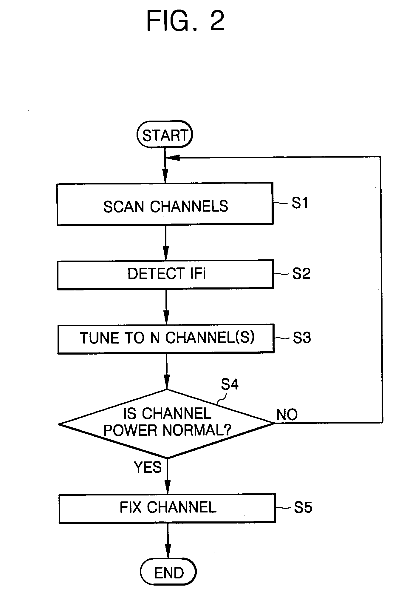
[0035] It is an object of the present invention to provide a power-saving channel scanning system and method for multi-channel broadcasting that stops a scanning operation of a digital tuner installed in a broadcast receiving device (STB) when a cable is cut off or no signal is received in the system, thus preventing a waste of electricity and a temperature rise of the system.
[0036] It is another object of the present invention to provide a power-saving channel scanning system and method for managing channel power of multi-channel broadcasting in real time, thus allowing a network manager to immediately recognize the situation to maintain the network when no RF signal is transmitted or a problem occurs in the transmission network.

Problems solved by technology

In other words, the broadcasting receiving method noted above has a problem in that when no RF signal is transmitted, e.g., when the cable is cut off, there is no signal, etc., the RF block, e.g., a tuner, etc., continues operating to find a channel even though there is no need to scan channels, and thus electricity is wasted and the overall temperature of the system increases.
In addition, when no RF signal is transmitted, e.g., when the cable is cut off, there is no signal, etc., or a problem occurs with the transmission network, the terminal cannot recognize the situation and the network manager has no way of knowing about the problem until complaints are finally received.

Method used


Image

  • Power-saving channel scanning for multi-channel broadcasting
  • Power-saving channel scanning for multi-channel broadcasting
  • Power-saving channel scanning for multi-channel broadcasting

Examples


Embodiment Construction

[0054]FIG. 1 is a block diagram of a digital tuner. Referring to FIG. 1, the digital tuner includes a tuning unit 10 and a demodulation unit 20. The tuning unit 10 includes an Automatic Gain Controller (AGC) 11, a Radio Frequency amplifier (RF amplifier) 12, a Radio Frequency Band Pass Filter (RF BPF) 13, a Phase-Locked Loop Integrated Circuit (PLL IC) 14, a local oscillator 15, a mixer 16, a Surface Acoustic Wave filter (SAW filter) 17, an Intermediate Frequency amplifier (IF amplifier) 18, and a Radio Frequency Automatic Gain Control detection circuit (RF AGC detection circuit) 19. An included demodulation unit 20 includes a demodulator IC 21 in which an Intermediate Frequency Automatic Gain Control detection circuit (IF AGC detection circuit) 22 is installed.

[0055] The AGC 11 automatically controls the gain such that the output power of a video signal is always constant despite a change in the magnitude of a high-frequency signal introduced through an antenna ANT.

[0056] The RF ...


PUM


Abstract

A power-saving channel scanning system and a method thereof for multi-channel broadcasting stops the scanning operation of a digital tuner installed in a broadcast receiving device (Set-Top Box (STB)) and switches to a power-saving mode when a cable is cut off or no signal is received in a multi-channel broadcasting system. The power-saving channel scanning system includes a broadcast receiving terminal measuring broadcasting channel powers in order and switching from a normal mode to a power-saving mode when the powers of all of the measured channels are outside the range of a predetermined normal channel power.

Description

CLAIM OF PRIORITY [0001] This application makes reference to, incorporates the same herein, and claims all benefits accruing under 35 U.S.C. §119 from an application for POWER-SAVING CHANNEL SCANNING SYSTEM AND METHOD FOR MULTI-CHANNEL BROADCASTING earlier filled in the Korean Intellectual Property Office on 1 Apr. 2005 and there duly assigned Serial No. 2005-27709. BACKGROUND OF THE INVENTION [0002] 1. Field of the Invention [0003] The present invention relates to a power-saving channel scanning system and method for multi-channel broadcasting, and more particularly, to a power-saving channel scanning system and method for multi-channel broadcasting that stops a scanning operation of a digital tuner installed in a broadcast receiving device (Set-Top Box (STB)) and switches to a power-saving mode when a cable is cut off or no signal is received. [0004] 2. Description of Related Art [0005] At present, in the early stages of digital broadcasting service, the number of digital and anal...

Claims


Application Information

Patent Timeline
IPC IPC(8): H04N7/173H04N5/44
CPCH04N5/4401H04N5/50H04N21/44209H04N21/4383H04N5/63H04N21/426
Inventor SEO, DONG-UK
Owner SAMSUNG ELECTRONICS CO LTD
Learn More